EasyManua.ls Logo

OTC Welbee M350 II User Manual

OTC Welbee M350 II
148 pages
To Next Page IconTo Next Page
Page #1 background imageLoading...
Page #1 background image
Welbee M350 II
M500 II
OWNER'S MANUAL
July, 2021
Manual No. : P30355-1
DAIHEN Corporation
Question and Answer IconNeed help?

Do you have a question about the OTC Welbee M350 II and is the answer not in the manual?

OTC Welbee M350 II Specifications

General IconGeneral
Rated Output Current350 A
Welding MethodMIG/MAG, MMA
Protection ClassIP21S
Cooling MethodForced air cooling
Output Current Range40 - 350 A
Welding Current Range40-350A
Duty Cycle60% at 350A
Wire Diameter Range0.8mm

Summary

Forward

Service and Support

Nameplate Attachment Location

Diagram illustrating the location of product information on the nameplate.

Important Information

Product Usage

Specifies the intended purpose and limitations of the welding power source.

Safe Product Use

Instructions and precautions for safe operation of the welding power source.

Copyright Information

States the copyright and reproduction rights of the manual.

Exporting the Product

Conditions to observe when exporting the product outside the country.

Product Disposal

Guidelines for proper disposal of welding equipment.

Chapter 1 Safety Information

Warning Symbols

Explanation of safety symbols used in the manual for hazard indication.

Safety Precautions

Operating Precautions

Important instructions to prevent serious injury or accidents during operation.

Power Supply and Electric Shock Precautions

Plastic Parts Handling Precautions

Disassembly and Modification Precautions

Air Discharge and Respiratory Protection

Protective Equipment Precautions

Flammable Materials Precautions

Gas Cylinder and Regulator Precautions

Rotating Part Precautions

Principal Safety Standards

Chapter 2 Product Specification and Configuration

Specifications Overview

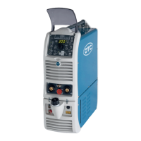
General overview of the product's specifications.

Detailed Specifications

Detailed specifications of the welding power source, including electrical and physical attributes.

Applicable Welding Methods

External Dimensions

Rated Duty Cycle

Product Configuration

Standard Composition

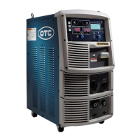
Details the standard components of the welding power source.

Required Customer-Supplied Accessories

Optional Accessories

Extension Cables and Hoses

Part Names

Front Panel Components

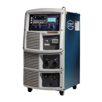
Identifies and labels the components on the front panel of the welding power source.

Rear Panel Components

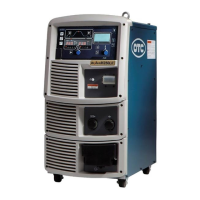
Identifies and labels the components on the rear panel of the welding power source.

Chapter 3 Transportation and Installation

Required Equipment

Lists necessary equipment for installing the welding power source.

Welding Power Source Equipment Details

Specifies the required ratings for welding power source equipment and protective devices.

Engine Generator and Auxiliary Power Use

Ventilation and Exhaust Facilities

Installation Environment

Installation Environment Details

Lists specific environmental conditions for safe and proper installation.

Electromagnetic Interference (EMI)

Transportation Procedure

Transportation Using Lifting Lug

Connection and Grounding Precautions

Connecting the Welding Power Source

Output Cable Connection

Procedure for connecting cables at the output terminals of the welding power source.

Wire Feeder Connection

Welding Torch Connection

TIG Welding Connection Specifics

DC Stick Welding Connection

Shield Gas Connection

Grounding and Input Power Connection

Connection Confirmation

External Equipment Connection

Robot Connection

Configuration example for connecting the welding power source with robots.

Automatic Machine Connection

External Connection Terminal

Voltage Detection Cable Wiring (Base Metal Side)

Wiring to Wire Feeder

Wiring to Welding Power Source

Voltage Detection Cable Wiring Examples

Chapter 5 Welding Operation

Welding Operation Precautions

Safety precautions specifically for welding operations.

Air Discharge and Respiratory Protection During Welding

Safety measures for ventilation and respiratory protection during welding.

Protective Equipment for Welding

Welding Place Precautions

Check Before Welding

Power ON and Gas Supply

Wire Inchng Operation

Check and Set Welding Conditions

Reading Welding Conditions

How to read and confirm registered welding conditions.

Erroneous Operation Prevention

Function to prevent accidental changes to welding conditions on the operation panel.

Performing Welding Operation

CO2/MAG Welding Procedure

Steps for performing CO2/MAG welding operations.

Other Welding Methods

Welding Operation During Welding

Operation at Welding End

Chapter 6 Welding Condition

Welding Conditions List

Lists parameters and functions settable in the welding power source.

Welding Parameters

Details various welding parameters like pre-flow, current, voltage, and arc characteristics.

Internal Functions

Detailed Information on Internal Functions

F1 Standard/Extended Cable Mode

Sets control status for extended cables in STANDARD mode.

F2 Remote Control Switching Functions

Assigns functions to the analog remote control's switching knob.

F4 Auto/Semi-auto Mode

F5 Maximum External Command Voltage

F6 Upslope Time

F7 Downslope Time

F8 Welding Result Display Time

F9 Analog Remote Control Scale

F10 Motor Over Current Detection Level

F11 Fine Adjustment of Welding Conditions Memory

F13 Turbo Start

F14/F15 Start Control Adjustment

F16 Slowdown Speed Adjustment

F17/F18 Anti-stick Time/Voltage Adjustment

F19 Switching Alarm Setting

F20 Low Input Voltage Detection Level

F21 Maximum Cooling Fan Operation

F25-F28 External Output Terminal Setting (reserved)

F29-F32 External Input Terminal Setting

F38 Arc Voltage Direct Detection Switching

F39/F40 Current Display Adjustment

F41/F42 Voltage Display Adjustment

F44 Reading Welding Conditions with Remote Control

F45/F46/F47 Special Crater Sequence

F48 Adjusting Current with Torch Switch

F49 Current Increase/Decrease (Single-Click)

F50 Current Increase/Decrease (Double-Click)

F51 Special Crater Repeat

F52 Data Type for Data Log

F53 Sampling Speed of Data Log Function

F54 Tack Start Process

F78 Unintended Torch Switch Operation Prevention

F79 CAN Communication Connection Device

F80 CAN Communication Speed

F81 TIG Mode Switch Setting

F83 Arc Length Adjustment (Post-Start)

Operation of Analog Remote Control (Optional)

Chapter 7 Administrator Functions

Protection of Welding Conditions

Explains the password function to protect welding conditions from accidental changes.

Setting and Changing Password

How to set and change the password for protection.

Disabling Erroneous Operation Prevention

Chapter 7.2 Welding Result Control Function

Setting Welding Result Control

How to set up the welding result control parameters.

Welding Monitor Parameters

Total Operating and Welding Time

Alarm Indication When Target Achieved

Alarm Indication for WARNING Detection

Chapter 7.3 Data Backup and Utilization

Setting Welding Conditions/Internal Functions for Backup

Specifies contents to be stored in backup files like CSV.

Simplified Data Log Function

Backup Operation

Importing Backup Data

Initializing Welding Conditions and Internal Functions

Checking Software Version and Serial Number

Chapter 7.6 Calibration Mode

Adjusting Output Current

Procedure for calibrating the output current value.

Adjusting Output Voltage

System Setting

Chapter 8 Maintenance and Inspection

Maintenance and Inspection Precautions

Safety precautions to follow during maintenance and inspection work.

Daily Inspection

Periodical Inspection

Periodical Replacement Parts

Insulation Resistance and Withstand Voltage Test

Chapter 9 Troubleshooting

Action in Case of Error

Describes how to cope with abnormalities indicated on the operation panel.

Chapter 10 Reference Materials

Parts List

Lists all parts of the welding power source with their part numbers.

Reference Drawings

WB-M502 Schematic Diagram

Schematic diagram for the WB-M502 model.

Parts Layout Drawings

WB-M352 Parts Layout

Parts layout drawing for the WB-M352 model.

Chapter 10.3 Materials for Setting Welding Conditions

Guide to Changing Welding Conditions

Explains problems arising from improper welding conditions and their symptoms.

Welding Conditions: I Shape Butt Joint

Welding Conditions: Horizontal Fillet Joint

Welding Conditions: Single/Double Grooves

Welding Conditions: Lap Fillet Joint

Example MAG Short Arc Welding Conditions

Example Aluminum MIG Welding Conditions

Related product manuals