User’s Guide of DO3000 Door Operator
Lead the green future All rights reserved © OTIS 6/48
2.2.1.2 HAA24360AE2 controller
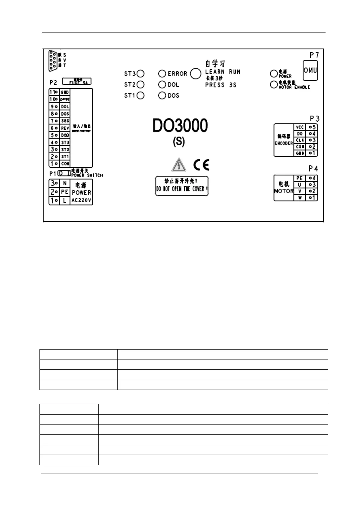
Fig.2-5 Controller case
The circles in the figure represent the indicator and learning button:
Power indicator: normally on when the power is normal.
Motor enable indicator: normally on when the motor strongly outputs.
ST1 / ST2 / ST3: ST code input signal, normally on when it is effective
DOS: turns on when the passenger protection is triggered.
DOL: normally on when the door is opened to the place
ERROR: normally on when the controller is out of service
Learning button: for the learning of controller angle and door width
2.2.1.3 Definitions and descriptions of input/output ports
Definitions and descriptions of terminals are as shown in the following table:
Power line:
PE: protection earthing wire
Input/output signals (Part number: HAA24360AK1~HAA24360AK4):
DC30V, power from host computer
 Loading...