
M
Matthew ZimmermanAug 3, 2025
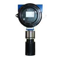
What to do if my OTIS GEN II OI-6000 shows 'F14 Check Radio'?
- WWendy BowmanAug 3, 2025
If your OTIS Other displays the error 'F14 Check Radio', it indicates that the sensor assembly has lost communication with the Primary Monitor. This can occur if the Network ID is incorrectly configured, the sensor assembly is obstructed or too far from the Primary Monitor, or the radio module is not working. First, verify that the Network ID on the sensor assembly matches the Primary Monitor Network ID. If the issue persists, move the sensor assembly away from any obstructions or consider using a high gain antenna. As a last resort, replace the sensor radio module.