Do you have a question about the Ouellet OTH557 and is the answer not in the manual?
Adapter plate is required only for OTH557 (347 V) models for installation.
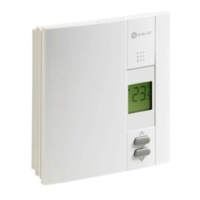
The OTH550 & OTH557 are electronic thermostats designed to manage electric heating systems. These include baseboard heaters, radiant ceilings, radiant floors, convectors, or fan-forced convectors.
The thermostats control the heating system by regulating the temperature. They feature a temperature display, showing the current temperature, and allow users to adjust the setpoint using dedicated buttons. A keypad lock function is available to prevent unauthorized changes to settings. The device also indicates heating intensity and displays a fan-forced heater icon when configured for such a system.
To ensure proper operation, the thermostats must be connected using solderless connectors for copper wires. The thermostat wires are non-polarized, meaning either wire can be connected to either terminal. For connections with aluminum conductors, special CO/ALR solderless connectors must be used because the thermostat has tinned copper wires.
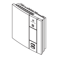
Installation involves mounting the wallplate to the electrical box. Configuration switches on the back of the thermostat's faceplate allow users to customize settings such as keypad lock, cycle length, and temperature display format (°C or °F). Short cycles (15 seconds) are generally recommended for better temperature control, but long cycles (5 minutes) should be selected for fan-forced heaters, indicated by a fan icon.
The configuration menu is accessed by simultaneously pressing the up and down buttons for three seconds. Users can navigate parameters using the up or down buttons and confirm selections by pressing both buttons simultaneously for one second to move to the next parameter. To exit the menu, both buttons are pressed simultaneously for three seconds. The thermostat automatically saves changes and returns to the normal display if no button is pressed for one minute.
The thermostat typically displays the actual temperature. To view the setpoint, either temperature adjustment button is pressed once, and the setpoint appears for five seconds, accompanied by a setpoint icon. To change the setpoint, the appropriate button is pressed until the desired value is displayed. The screen is backlit for 10 seconds when any button is pressed.
In the event of a power outage, the setpoint is saved in memory, eliminating the need to readjust the temperature when power is restored.
For optimal performance, the air vents of the thermostat must be kept clean and unobstructed at all times. If a protective film or sticker is present on the screen, it should be peeled off after installation.
Troubleshooting guidance is provided for common issues. If the thermostat's housing feels hot, this is normal when it operates at full capacity, as its housing can reach 40 °C (104 °F). If an incorrect temperature is displayed, users should check for air drafts, ensure any screen stickers have been removed, and verify that the thermostat is not near a heat source like a light dimmer. If the display disappears and reappears, it may indicate that the heater's thermal protection device has temporarily opened due to obstruction by furniture or curtains, or if the device is too sensitive.
The installation must be carried out by a qualified electrician and comply with local electrical codes. Before any work, power to the heating system at the main electrical panel must be cut to avoid electrical shock. The thermostat is supplied with mounting screws, solderless connectors, and an adapter plate (for OTH557 only).
The OTH550 & OTH557 thermostats are not suitable for resistive loads under 1.25 A (OTH550) or 2 A (OTH557), resistive loads over 16.7 A, systems driven by a contactor or relay (inductive loads), or central heating systems.
Ouellet Canada Inc. provides a three-year limited warranty covering defects in material and workmanship under normal use and service, provided proof of purchase is supplied. The warranty covers the supply of a new unit, excluding installation costs or other secondary charges. Customer assistance is available via phone, fax, or email for any product-related questions.
| Temperature Range | 5°C to 30°C (41°F to 86°F) |
|---|---|
| Display | LCD |
| Power Supply | Line Voltage |
| Mounting | Wall |
| Voltage | 120/208/240 VAC |
| Control Type | Electronic |