©2016 Universal Forest Products, Inc. Outdoor Essentials is a registered trademark of Universal Forest Products, Inc. All rights reserved.
68956 U.S. Hwy 131, White Pigeon, MI 49099 616.365.4201 8902_7/16
www.outdooressentialproducts.com
THE DIAGRAMS AND INSTRUCTIONS IN THIS BROCHURE ARE FOR ILLUSTRATION PURPOSES ONLY AND ARE NOT MEANT TO REPLACE A LICENSED PROFESSIONAL. ANY CONSTRUCTION OR
USE OF THE PRODUCT MUST BE IN ACCORDANCE WITH ALL LOCAL ZONING AND/OR BUILDING CODES. THE CONSUMER ASSUMES ALL RISKS AND LIABILITY ASSOCIATED WITH THE
CONSTRUCTION OR USE OF THIS PRODUCT. THE CONSUMER OR CONTRACTOR SHOULD TAKE ALL NECESSARY STEPS TO ENSURE THE SAFETY OF EVERYONE INVOLVED IN THE PROJECT,
INCLUDING, BUT NOT LIMITED TO, WEARING THE APPROPRIATE SAFETY EQUIPMENT. EXCEPT AS CONTAINED IN THE WRITTEN LIMITED WARRANTY, THE WARRANTOR DOES NOT
PROVIDE ANY OTHER WARRANTY, EITHER EXPRESS OR IMPLIED, AND SHALL NOT BE LIABLE FOR ANY DAMAGES, INCLUDING CONSEQUENTIAL DAMAGES.
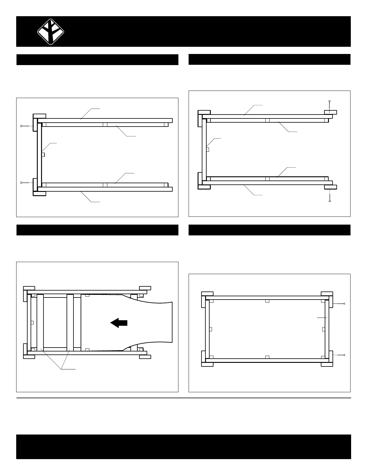
STEP 3
STEP 6
Place the legs with the side assemblies attached approxi-
mately 21" apart. Slide the end assembly between the two
legs and fasten through the predrilled holes (fig. 3).
Slide the end assembly between the two legs. Place "B1" and
"B2" against the end assembly fasten through the predrilled
holes (fig. 6). Attach “A1” to “B1” and “A2” to “B2” through the
predrilled holes.
End Assembly
Side Assembly
Side Assembly
Ledger
•
•
•
Ledger
•
•
End Assembly
A1 A2
A2
B1B2
B2B1
A1
•
fig. 3
STEP 5
Place four bottom supports in the assembly. Slide the plastic
tray through the open end over the bottom supports (fig. 5).
Supports
Plastic Tray
•
•
fig. 5 fig. 6
ELEVATED GARDEN PLANTER INSTALLATION INSTRUCTIONS
STEP 4
Leaving a ¾" overhang, attach “A1” and “A2” to the side
assemblies through the predrilled holes (fig. 4).
End Assembly
Side Assembly
Side Assembly A2
A1
Ledger
•
•
•
Ledger
•
•
fig. 4
 Loading...