'''1
36
-.-0-
(
&
C-*>-2*-
L%3E
:
7 "
7 =; '$0?%$ "
,", D
7 7N!%O*./ >,0
7 )N)7M./ ">,0ON3CDP./ $>,0O*
7 -E
,"- %=%;>?
-./ >10-9
-ND4HL)!%O
7 =>-N%H%4%D'R6%44=3%O
&
=-N%H%4%D'R6%44=3%O>(-
,". %E+9
7 %9(
7 !-9(2
7 7
%96
7 :!!"! B"
,"0 2
Q
3
&424
D:-(
(>-8
7 ?
7 =>?
7 !-2
7 L
7 C2-
,"'1 !
23/&424
3
7 72
7 7./ >10--
7 4--
7
Press the fuse insert back into the housing.
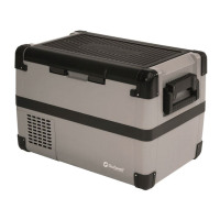
6.11 R e p l a c i n g t h e p l u g f u s e ( 1 2 / 2 4 V )
Turn anticlockwise the cap (fig. 1) to move it and pin (fig.
3) with a new one that has the same rating
Re-assemble the plug in the reverse order.
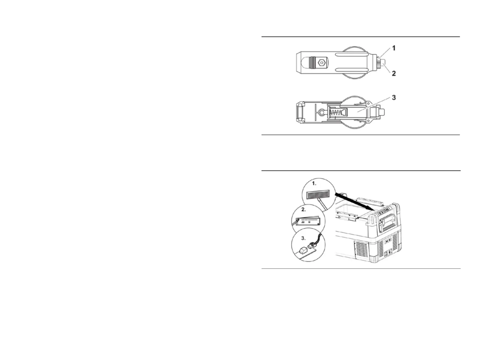
6.12 Replacing the light PCB
Unscrew the PCB mounting screws(fig.
Replace the defective light PCB with a new one.
Fit new PCB using reverse of removal instructions.
Press the transparent cover back into the housing.
• 2) from the plug.
• Press one end of defective fuse (fig.
•
Pry out the transparent cover with a screwdriver (fig. 1 )
2 )
Pull out the plug from the PCB(fig. 3 )
•
INSTRUCTIONS INSTRUCTIONS
 Loading...