Do you have a question about the OVER OCTOPUS and is the answer not in the manual?
Details the 4 digital input model with its product code and description.
Details the 3 digital output model with its product code and description.
Details the 1 analog input model with its product code and description.
Details the 1 analog output and 1 digital output model.
Provides essential safety warnings and handling instructions for the instrument.
Explains the wiring and status display for the 4 digital inputs model.
Explains the wiring and status display for the 3 digital outputs model.
Explains the wiring and status display for the 1 analog input model.
Explains the wiring and status display for combined output models.
Describes the meaning of different colors and states for the device's LEDs.
Explains how the three-digit LED display shows model and connection status.
Details the additional screen showing status for each of the 4 digital inputs.
Details the additional screen showing status for each of the 3 digital outputs.
Details the additional screen showing analog input voltage or current.
Details the additional screen showing analog output and digital output status.
Diagram illustrating the wiring for the 4 digital inputs configuration.
Diagram illustrating the wiring for the 3 digital outputs configuration.
Diagram illustrating the wiring for the analog input configuration.
Diagram for wiring the analog output and digital output configuration.
The OCTOPUS is a bus interface designed to facilitate interaction between the OVER Building Energy Management System (BEMS) and various generic devices, including digital/analog sensors, dry contacts, and voltage contacts. It features a customizable interface, allowing for flexibility in integration with different systems. The device is built with a main electronic base that can accommodate interchangeable specific interfaces, each offering distinct features.
The primary function of the OCTOPUS is to act as a bridge, enabling the OVER BEMS to communicate with and control a wide range of external devices. This includes handling digital inputs and outputs, as well as analog inputs and outputs. The customizable nature of its interface means it can be adapted to various application requirements by plugging in different interface modules.
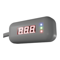
The device features a front-facing LED display and three signaling LEDs. The LED display provides information about the device's model and connection status, continuously refreshing to show updated information. Screens with text longer than three digits automatically scroll to display the full information. Common screens across all OCTOPUS devices show the model number, device address, and firmware revision. Additional screens, which vary depending on the specific OCTOPUS model, provide more detailed information relevant to that configuration. For instance, the 4 Digital Inputs model displays the status (open or closed) of each digital input, while the 3 Digital Outputs model shows the on/off status of each digital output. The 1 Analog Input model provides the analog input status, indicating voltage (V) or current (mA), and the 1 Analog Output + 1 Digital Output model shows the analog output status (as a percentage) and the digital output status (on or off).
The three signaling LEDs indicate different states of the device:
The OCTOPUS communicates via the EDS bus, and the number and type of wires in the cable vary depending on the installed shield. Connection diagrams are provided for different configurations, such as 4 Digital Inputs, 3 Digital Outputs, Analog Input, and 1 Analog Output + 1 Digital Output, detailing how to connect the device according to its intended use.
The OCTOPUS is designed for ease of integration into existing BEMS environments. Its customizable interface allows users to select specific modules that match their device requirements, making it a versatile tool for various applications. The LED display and signaling LEDs provide immediate visual feedback on the device's operational status, aiding in quick diagnostics and monitoring. The compact size (68x31x24 mm) and light weight (40g) make it suitable for installation in diverse locations. The wide operating and warehousing temperature ranges (-40°C to +85°C) ensure reliability in challenging environmental conditions. The device's power supply requirement of 12-15 Vdc and low current draw (max 30mA) contribute to energy efficiency.
The manual emphasizes several safety guidelines crucial for the proper functioning and longevity of the device, which can be considered maintenance-related:
These guidelines ensure that the device is handled correctly, minimizing the risk of damage and ensuring safe operation, which are key aspects of device maintenance. The modular design, allowing for interchangeable interfaces, could also simplify maintenance by enabling the replacement of specific interface modules rather than the entire unit if a component fails.
| Brand | OVER |
|---|---|
| Model | OCTOPUS |
| Category | Recording Equipment |
| Language | English |