OWI User Manual: Model AMP1SGRN Speaker Amplifier with Priority Audio Override
OWI Model AMP1SGRN Manual Page 18 of 28
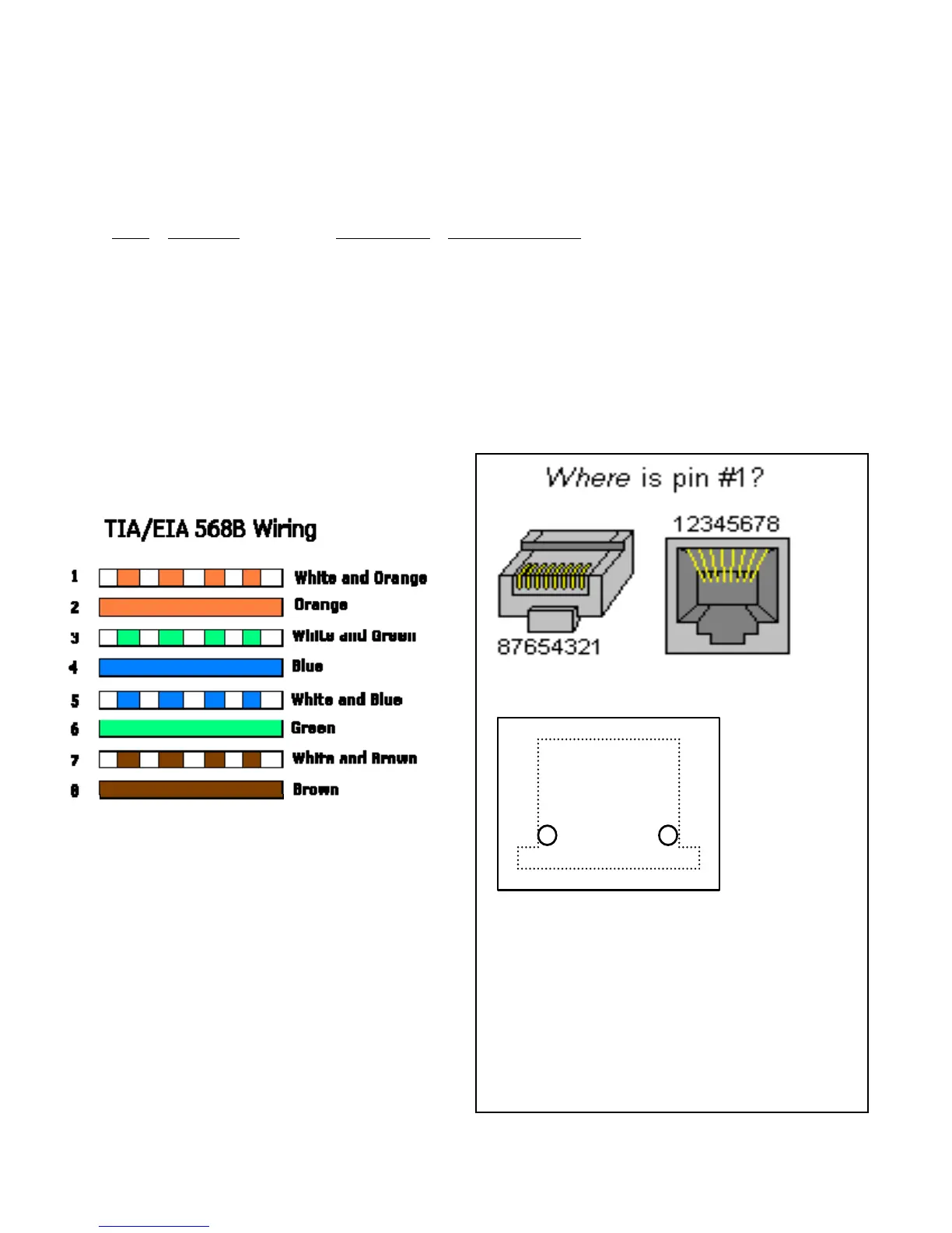
RJ45 PIN-OUT
TIA/EIA-
568-B.1-
2001 T568B
Wiring
Pin# Function Color Code DE9 (Was DB9)
1 RS232 TX White/Or 3 Transmit into PC Receive
2 RS232 RX Orange 2 Receive into PC Transmit
3 RS232 Gnd White/Grn 5 Ground
4 Power +15VDC Blue
5 Power Ground White/Blu
6 Shield Ground Green
7 Line In+, TB1-3 White/Brn Non-Priority
8 Line In-, TB1-2 Brown Non-Priority
Cable Wiring Schemes
Plug Receptacle
7 6 5 1
8 4 3 2
CAT5/CAT3 Jack
Non Traditional Board Layout
Note: The RJ-45 connector is on the
component side. Shown here are the
pins poking through from the component
side of the board to the solder side of the
board. But the connector pin-out is standard
as pictured above.


 To Next Page