EasyManua.ls Logo

Oxygen CASTOR - User Manual

Default Icon
3 pages
Print Icon
To Next Page IconTo Next Page
Loading...
CASTOR
INSTALLATION MANUAL
Our compliments for your excellent choice. The Castor electro-
mechanical gear motor has been produced for reliability and high
quality.
This Manual will offer information you may need to install your gear
motor assuring long-lasting performance and to safeguard your safety.
HOWEVER CAUTION IS UNQUESTIONABLY INDISPENSABLE
AND NOTHING IS BETTER THAN PREVENTING ACCIDENTS.
Our products have been made to conform with rules and laws in force
at time of manufacture.
This manual is designed exclusively for the specialized
installation expert in the criteria of construction and equipment to
assist in the protection against accidents in the installation and use of
the gate; door and automation of such gates (adhere to the rules and
laws in force).
On completion the installer should issue to the end consumer an
instruction manual according to EN 12635.
Before proceeding with the installation the installer must provide
an analysis of the identification and management of risks as per the
standards EN 12453 and EN 12445.
All wiring of the various external electrical components
connected to the automation (e.g. Photocells, flashing lights, keypads
etc) must be carried out according to EN 60204-1 and the
amendments made of the point 5.2.2 of EN 12453.
It is prohibited to do any repair or adjustment of the equipment if
you have not taken all necessary precautions to avoid possible
accidents (example: power supply disconnected, engine block). All
mechanisms in motion must be equipped with appropriate protections.
The mains power line must be protected for maximum current in
locked rotor condition as per government electrical laws.
Install the gear motor on gates that conform to EN 12604.
Perform the measure of strength developed by the gear motor
and take the appropriate steps as per EN 12445.
Positioning photocells: These safety devices must be installed at
a height not exceeding 70cm from the ground and at a distance from
the floor movement of the door of no more than 20cm. Their proper
functioning of the photocells must be verified at the end of installation
according to Section 7.2.1 of EN12445.
Keep the activation controls of automation out of reach of
children. The controls should be installed at a minimum 1.5m height
above the ground and outside the range of actions of moving parts
such as the gate.
All activation actions must be executed only at points from
where the automation is fully visible.
Operate the remote only in view of automation.
Store carefully this manual in a suitable place known to all
interested people.
Any unauthorized and arbitrary modification made to this
product, releases the company Oxygen Automation and from any
liability resulting from damage or injury to things, people or animals.
The non-observance of regulations and of safety standards here
listed releases the company Oxygen Automation from any liability
resulting from damage or injury to things, people or animals.
The automation must be coupled to a control board equipped
with torque regulation that provides an anti crushing safety as
described in EN 12453 - EN 12445
SAFETY RULES
During the installation and the use of the automation, pay attention to
the following safety rules:
Distance security!
Mechanisms moving!
Do not install automation in an environment saturated with
explosive mixtures!
Electric Shock!
Use gloves!
Use welding glasses!
Maintain ear protection!
MAINTENANCE
All repairs must be carried out by qualified people.
Before each intervention remove power through the switch and
lock in that position
The equipment must be maintained so as to preserve the
conditions that ensure safe and efficient operation
Always use original spare parts
Do not make interventions that modify the machine.
The modified equipment requires new CE mark
The settings of the operator must be performed by qualified
personnel, in accordance with the rules of reference. During these
operations provide the presence of two operators for safety.
DEMOLITION
You have to operate the elimination of the materials in conformity with
the regulations in force. All materials must be divided by type (copper,
aluminium, plastic, electrical parts, etc)
USE OF THE AUTOMATION
The gearmotor Castor was designed and built for the opening of gates
with max of 3,5 m leaf or weight max. 200kg. Oxygen Automation
Question and Answer IconNeed help?

Do you have a question about the Oxygen CASTOR and is the answer not in the manual?

Overview

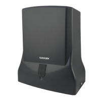
The Castor electro-mechanical gear motor is designed for the automation of gates, offering reliability and high quality. It is intended for specialized installation experts and comes with a comprehensive manual to ensure long-lasting performance and user safety. The product conforms to relevant rules and laws in force at the time of manufacture, including EN 12635, EN 12453, EN 12445, EN 60204-1, EN 60335-1, EN 292/1/2, EN 294, 89/392/CEE (Machine Directive), 89/336/CEE (Electromagnetic compatibility Directive), and 73/23/CEE (Low tension Directive).

Function Description:

The Castor gear motor is built for opening gates with a maximum leaf length of 3.5 meters and a maximum weight of 200 kg. It provides automated gate operation, enhancing convenience and security. The system is designed to be coupled with a control board that includes torque regulation for anti-crushing safety, as described in EN 12453 and EN 12445. The manual emphasizes that any unauthorized modifications to the product will release the manufacturer, Oxygen Automation, from any liability for damage or injury.

Important Technical Specifications:

The Castor gear motor is available in two models: CASTOR 230V and CASTOR 24V.

  • CASTOR 230V:

    • Maximum length of the gate: 3.5 m
    • Maximum weight of the gate: 200 Kg
    • Stroke: 40 cm
    • Power: 350 W
    • Power supply: 220 V
    • Absorption: 1.5 A
    • Operating temperature: -25°C to +60°C
    • Opening time: 17 sec.
    • Thermal protection: 150°C
    • Use frequency: 35%
    • Lubrication: GREASE
  • CASTOR 24V:

    • Maximum length of the gate: 3.5 m
    • Maximum weight of the gate: 200 Kg
    • Stroke: 40 cm
    • Power: 70 W
    • Power supply: 24 V
    • Absorption: 0.5 - 5.5 A
    • Operating temperature: -25°C to +60°C
    • Opening time: 17 sec.
    • Use frequency: 80%
    • Lubrication: GREASE

Usage Features:

The installation process requires careful adherence to safety rules and preliminary checks. Before installation, an analysis of risks must be performed according to EN 12453 and EN 12445. All wiring of external electrical components (photocells, flashing lights, keypads, etc.) must comply with EN 60204-1. The gear motor should only be installed on gates conforming to EN 12604.

Key installation steps include:

  1. Opening the packaging and checking for transport damage.
  2. Ensuring the gate is perfectly horizontal and moves freely.
  3. Releasing the motor for emergency release.
  4. Fixing the pillar plate A on the side of the door, respecting specified allowances (e.g., 145mm for 95° rotation, 170mm for 120° rotation).
  5. Installing the motor on plate A and securing it with a pin and grub screw.
  6. With the door closed, sliding the mounting pin F and mechanical stopper D to the end of the run, then fixing pin F to plate B.
  7. Securing support plate B to the leaf, fastening the motor with pin F, and checking/fixing stopper D.
  8. Opening the door to the desired open position and fixing limit switch E.
  9. Repeating steps for the other gate leaf (if applicable).
  10. Carrying out wiring and fitting safety devices.
  11. Positioning the cover cap C on the release pin.

Safety rules during installation and use include:

  • Maintaining a safe distance from moving mechanisms.
  • Avoiding installation in environments with explosive mixtures.
  • Taking precautions against electric shock.
  • Using gloves, welding glasses, and ear protection.
  • Ensuring the mains power line is protected for maximum current in locked rotor conditions.
  • Installing photocells at a height not exceeding 70 cm from the ground and no more than 20 cm from the door's movement path.
  • Placing activation controls out of reach of children, at a minimum height of 1.5 m above the ground, and outside the range of moving parts.
  • Executing activation actions only from points where the automation is fully visible.
  • Operating the remote control only when the automation is in view.

Emergency Manoeuvre:

For manual door locking and unlocking, use the supplied key on screw H.

  1. Remove protection cap C.
  2. Insert the key into the seat.
  3. Turn the key clockwise to block and anti-clockwise to release.

Maintenance Features:

Regular maintenance is crucial for safe and efficient operation.

  • All repairs must be carried out by qualified personnel.
  • Before any intervention, power must be removed via the switch and locked in position.
  • Only original spare parts should be used.
  • Interventions that modify the machine are prohibited, as modified equipment requires a new CE mark.
  • Settings of the operator must be performed by qualified personnel, with two operators present for safety.

Scheduled maintenance tasks:

  • Photocells cleaning: Monthly, performed by the operator, using a damp cloth.
  • Control of gate hinges and supports, balancing of the gate: Annual, performed by the operator, checking welds, corrosion, and gate balance.
  • Controlling the sensitivity of electronic friction (torque adjustment) of the control board: Semiannual, performed by a technician, checking adjustment as per EN 12453 - EN 12445.
  • Monitoring current dispersion: Annual, performed by a technician, verifying current dispersion is less than 7.5 A.
  • Control of signals: Semiannual, performed by the operator, verifying safety warning signage is complete and intact.

The manual also emphasizes the importance of periodic checks (every six months) of the electronic friction regulation to ensure the perfect efficiency of all safety devices.

Dismantling:

To dismantle the automation:

  1. Cut off the power supply and disconnect the electrical installation.
  2. Dismantle the control console and all other components. Damaged components must be replaced.

Demolition:

Materials must be disposed of in conformity with regulations, separated by type (copper, aluminum, plastic, electrical parts, etc.).

Oxygen CASTOR Specifications

General IconGeneral
BrandOxygen
ModelCASTOR
CategoryEngine
LanguageEnglish

Related product manuals