EasyManua.ls Logo

OZGENC MAKINA SL 500 - User Manual

OZGENC MAKINA SL 500
74 pages
Print Icon
To Next Page IconTo Next Page
Loading...
OPERATOR'S MANUAL
AUTOMATIC ALUMINUM BLOCK CUTTING MACHINE
OPERATOR'S MANUAL
AUTOMATIC ALUMINUM BLOCK CUTTING MACHINE
www.ozgencmakina.com.tr
AUTOMATIC ALUMINUM BLOCK CUTTING MACHINE

Table of Contents

Other manuals for OZGENC MAKINA SL 500

Question and Answer IconNeed help?

Do you have a question about the OZGENC MAKINA SL 500 and is the answer not in the manual?

Summary

General Information

1. Document Publication Information

Information regarding publication details, revision, and year.

Documentation and CE Compliance

Procedures to Be Followed

Warning Symbols and Safety Messages

Explanation of warning symbols and their associated safety precautions.

Scope of User Manual

Machine Description

Machine Options

Information regarding available options for the SL 500 Aluminum block cutting machine.

Machine Cutting Capacity

Machine Specifications

Machine Layout and Unit Structure

Key Machine Component Identification

Labels identifying major units like covers, cabinets, and control panels.

Additional Component Identification

Panel and Reservoir Identification

Conveyor Structure Identification

Machine General Measurements

Machine Layout and Working Space

Work Safety and Precautions

Safety Switch Operation

Information on the function and importance of the safety switch.

Safety Measures and Accident Prevention

Detailed measures to prevent accidents and ensure user safety.

Machine Usage and Misuse Guidelines

Guidelines on correct machine operation and identification of improper usage.

General Safety Rules

Maintenance Safety Measures

Electricity Safety Rules

Lighting Conditions for Safe Operation

Wiring and Electrical Installation

Grounding System Requirements

Safety Equipment Overview

Main Switch and Cover Security Switch

Description and function of the main power switch and cover security switch.

Emergency;Stop Button

Risk Areas and Warnings

Electrical and Mechanical Hazards

Warnings about electric shock, moving parts, hot equipment, and pinch points.

Safe Operation and Manual Reference

Guidelines for safe machine interaction and the importance of consulting the user manual.

Noise Propagation

Disposal of Harmful Substances

Machine Start-Up Procedures

Domestic Transportation

Guidelines for packaging, handling, and transporting the machine domestically.

Loading and Vehicle Transfer

Overseas Transportation

Transportation Breakdown Check

Machine Installation Process

Machine Placement

Guidelines for positioning the machine in the designated facility area.

Ground Fixing Requirements

Specifications for securing the machine to the ground, including bolt size.

Start-up Preparation Steps

Electrical Connection Specifications

Electrical Panel Diagram and Equipment

Electrical Panel Component Identification

Labels identifying connector groups, drivers, power supply, relays, fuses, and PLC.

Machine Sensors and Functions

Position and Material Detection Sensors

Identification and function of forward/back limit and material detection sensors.

Reset and Back Limit Sensors

Pneumatic Connections and Air Supply

Machine Operation

Machine Start and Stop Procedures

Procedure for safely starting and stopping the machine.

Opening the Machine

Steps for turning on the main switch and checking the emergency stop button.

Control List and Safety Notes

Electrical Phase Sequence Warning

Important note regarding phase reversal and qualified electrician intervention.

Control Panel and Specifications

Moving Equipment on Machine

Profile Thrust;Fixation Pistons

Identification of pistons that thrust and fix profiles.

Slide Groups and Control Panel

Identification of slide groups and the user control panel.

Saw and Piston Components

Cutting and Machine Settings

Main Menu Options

Description of MANUAL MODE, AUTOMATIC MODE, PROGRAMMING, and SETTINGS.

Manual Operation Mode

Manual Mode Operation Interface

Manual Mode Controls and Functions

Explanation of pistons, saw operation, driving mechanism, reset, and cutting start controls.

Thrust Piston Identification and Reset Function

Numeric Value Entry for Cutting

Initiating Cutting Process

Automatic Operation Mode

Automatic Mode and Recipe Programming

Steps for entering automatic mode, recipe page, and work order commands.

Work List Page Operation

Part Data Entry for Work List

Explanation of entering part lengths and quantities on the work list page.

Automatic Mode Operation and Controls

Automatic Cutting Parameters and Steps

Explanation of cutting size, time, quantity, and starting the automatic cutting process.

Profile Loading and Cover Closure

Settings Page Parameters

Measurement Calibration and Servo Speed

Details on precise calibration and ratio of servo engine speed.

Saw Thickness Calibration

Explanation of saw thickness calibration for general machine setup.

Manually Setting Saw Output Speed

Saw Speed Adjustment Note

Important note on decreasing speed for better cutting quality and saw longevity.

Engine Belt Replacement Process

Engine Belt Replacement Steps

Instructions on turning off the switch, removing screws, and accessing the belt cover.

Engine Belt Adjustment and Replacement

Saw Replacement Procedure

Saw Replacement Precautions

Steps to interrupt air/electrical, remove lock nuts, and reverse the replacement procedure.

Fixation;Thrust Piston Control and Speed Setting

Thrust;Fixation Piston 1 Control

Adjusting Pressing Power of Upper Pistons

Ergonomics and Operator Convenience

Problem Determination Chart

Machine Failure Troubleshooting Guide

Table for diagnosing and resolving issues like no power, piston malfunction, or engine problems.

Alarm Codes and Meanings

General Maintenance Subjects

General Maintenance Schedule and Recommendations

Covers daily, weekly, monthly tasks, recommended oils, and coolant control.

Conditioner Water Level Control

Conditioner Lubricant Level Control

Cylinder Settings Adjustment

Cylinder Sensor Setting

Maintenance of Pneumatic Filters

Warranty Conditions and Terms

Exclusions from Warranty Coverage

Appendix Section

Technical Diagrams and Lists

Includes electrical circuit, pneumatic scheme, and parts lists.

Electrical Circuit Diagram Details

PLC and Servo Driver Connections

PLC and Encoder Interface Connections

Touchwin and Servo Driver Interface

PLC Module and Motor Driver Wiring

Machine Pneumatic Scheme

Exploded Pictures and Material List

Exploded View of Machine Parts

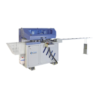
Visual representation of various machine components with numbered callouts.

Exploded View of Machine Parts - 2

Detailed Parts List - 1

Exploded View of Machine Parts - 3

Detailed Parts List - 2

Machine Body and Cutting Unit Parts

OZGENC MAKINA SL 500 Specifications

General IconGeneral
BrandOZGENC MAKINA
ModelSL 500
CategoryIndustrial Equipment
LanguageEnglish