Property of P-Q Controls, Inc. www.p-qcontrols.com
Features
♦ Independent Low Current Adjustment
♦ Independent Mid Current Adjustment
♦ Independent Hi Current Adjustment
♦ Adjustable RAMP
♦ Adjustable PWM Frequency
♦ Dual Output Range (Mid/Hi)
♦ Swap Feature
♦ RAMP Duration Between MID and HI Ranges
♦ Current Sourcing w/Feedback Outputs
♦ 2.5 Amp FET On/Off Outputs
♦ Over-Signal Protection
♦ Short Circuit Protection
♦ Reverse Polarity Protection
♦ Voltage Supply Transient Protection
♦ EMI and RFI Resistant
Description
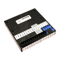
The Model 504 series of valve drive boards are an electronic interface between a command source
(potentiometer, joystick, footpedal, etc.) and an electro-hydraulic valve or pump. The board receives
analog signals from the command source, and provides Pulse Width Modulated Output (PWM) to drive
most electrically modulated valves and pumps available today. The board also provides On/Off Outputs
and other features to smoothly stroke a valve or pump with greater control and flexibility over
conventional hydraulic components. The 504 family of valve drive boards are designed for use on mobile
equipment where extreme environments (both weather and electrical) are encountered. The boards also
offer features used in many industrial applications. The 504 board can be mounted directly to P-Q single
axis joysticks or can be remotely mounted up to 100 feet from the command source.
Output from the proportional channels is Pulse Width Modulated (PWM) with current monitoring. The
Model 504 boards can be configured to drive single coil, dual coil, single coil (flow control) grounded
coil valves, or single coil floating valves. The proportional current output will remain fixed within 2%
during supply voltage swings, and coil resistance changes, (which occurs as the valve coil temperature
rises). Light emitting diodes (LED’s) are lit whenever the command signal exceeds the board’s deadband
and the board begins to output. Should any of the outputs (digital or proportional) be shorted, the outputs
will automatically shut down.