EasyManua.ls Logo

Paccar SM001-300 User Manual

Paccar SM001-300
39 pages
To Next Page IconTo Next Page
Page #1 background imageLoading...
Page #1 background image
SERVICE
M
ANUAL
Section
HVAC
Title Idle Management System Service Manual
Number
SM001-300
Date Rev. 9 © 9/2016
Model All w/ Idle Management System
Page 1 of 39
Kenworth Idle Management System
Technical Information and Diagnostic Guide
HVAC
PM820010 Rev. 9 © 9/2016
This guide will assist you in becoming more familiar with the working components
of the Kenworth Idle Management System and the proper steps and procedures to
completely diagnose the Kenworth Idle Management System unit.
©2016 PACCAR Corporation
Confidentiality Notice: This document and the information contained h
erein is proprietary. It shall not be reproduced, copied or disclosed,
in whole or in part, or used for manufacture without the written permission of PACCAR. You are hereby notified that any dissemination of
this information is strictly prohibited.

Table of Contents

Question and Answer IconNeed help?

Do you have a question about the Paccar SM001-300 and is the answer not in the manual?

Paccar SM001-300 Specifications

General IconGeneral
BrandPaccar
ModelSM001-300
CategoryMeasuring Instruments
LanguageEnglish

Summary

GENERAL SAFEY INSTRUCTIONS

Warnings, Cautions, and Notes

Explains the use of symbols and signal words for alerts and information.

Refrigerant and Oil Handling Precautions

Safety guidelines for handling specific refrigerants and oils, emphasizing compatibility.

Important Safety Notices

General safety rules for work area, attire, tools, and chemical handling.

EXTERNAL COMPONENT IDENTIFICATION AND LOCATION

Fuses and Relays

Identifies and describes the purpose of fuses and the function of relays.

Control Display and Controllers

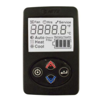
Describes the control interface and system/compressor controllers.

Key Modules and Sensors

Explains modules like the Linear Power Module and sensors like the temperature sensor.

Battery Systems

Details the Battery Management System and Battery Separator.

INTERNAL COMPONENTS

Pressure and Thermal Switches

Describes high pressure and thermal limit switches protecting the compressor.

Compressor and Evaporator Filter

Identifies the compressor and the evaporator inlet filter.

A/C System Diagnostic

ESPAR Heating System Diagnostic Table

Appendix

Battery and Control System Checks

Discusses battery condition, performance, and control display voltage checks.

Relay, Pressure Switch, and Fuse Testing

Provides steps for testing relays, pressure switches, and fuses.

Sensor and Controller Testing

Details testing procedures for sensors and the main controller.

Component Motor and System Testing

Outlines testing for fan motors, blower motor, and compressor mounts.

Specialized System Testing

Covers testing for BMS, Can Bus, and Espar Heater connectivity.

Service Instructions for Ring Terminal / Controller and Compressor

Operation

Basic System Operation

Covers starting the system, changing mode, blower speed, and temperature.

Advanced Operation and Diagnostics

Explains viewing runtime, unit conversion, and entering service mode.

Service Screens

Displays system parameters like battery voltage and amperage draw.