4
ASSEMBLY INSTRUCTIONS
Installation Requirements
Your P
ROPLUS
II
should be installed indoors on a flat, level surface near a 120Volt/ 15Amp outlet. PaceMaster requires a dedicated, non-
switched outlet that is not part of a GFI (Ground Fault Interrupter) circuit, preferably no more than 5 feet from the outlet to eliminate the need
for an extension cord. You must have a minimum of 4 feet of clearance between the rear of the treadmill and any wall or obstruction.
TIP: If you are installing your ProPlus
II
on a carpeted surface, use a treadmill mat or a scrap piece of carpet underneath the treadmill to
avoid soiling of the carpet. Deep pile carpet is not recommended.
Unpacking Your Treadmill
The PaceMaster treadmill is packed in five pieces:
• Frame assembly
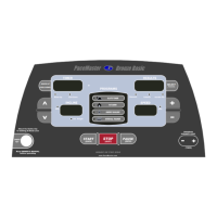
• Front handlebar assembly with Control Panel
• Two side rails
• Motor cover
• Hardware package
Before assembling your treadmill, open the hardware package and verify that you have the following items:
Two black side rail brackets Two #8 x ½” black sheet metal screws
Two 1” fender washers 3/16” Allen wrench
Four 1/4-20 x 3.5" black carriage bolt Magnetic safety key with garment clip
Two 1/4-20 x 4” black carriage bolt Owner’s Manual
Six 1/4-20 kep nuts Warranty registration card
If any parts are missing, contact the authorized PaceMaster retailer where you purchased your PaceMaster treadmill.
Tools Required for Assembly
• 3/16" Allen wrench (supplied)
• 7/16” combination wrench
• Phillips head screwdriver