EasyManua.ls Logo

PAIDI SOPHIA User Manual

PAIDI SOPHIA
5 pages
To Next Page IconTo Next Page
Page #1 background imageLoading...
Page #1 background image
Gebrauchsanleitung / Instructions / Mode demploi /
Gebruiksaanwijzing / Instrucciones
PAIDI
Möbel GmbH
Hauptstraße 87
D-97840 Hafenlohr/Main
ca. 1,5h
1:1
DIN A3
1 2 3 4 5 6 7 8 9 10 11 12
H19730058
5x
683 0011
Y
ø5,5
mm
9x
681 0770
C
27x
681 0351
D
16x
683 0061
X
ø5
mm
8x
683 0051
V
ø10
mm
9x
681 0852
6x
683 0021
Z
ø7
mm
4x
681 1597
E1
Klebepunkt
adhesive point
point de collage
punt voor het plakken
8x
681 5839
A
Größe 6
1x
681 3015
4x
681 7481
P
8x
681 7482
E
9x
681 7485
W
PK-Nr. 2160 Stand 02/12 Blatt 1 von 5 Ä: 07/19
G
D
4x
681 0801
M
1x
681 1664
G
Größe 4
1x
681 3011
3x
681 5714
H
1x
4
5
1
2
4x
681 5844
F
wmf plot 0,5 / 0,5
wmf plot 0,5 / 0,5
wmf plot 0,5 / 0,5
! !
SOPHIA
120 8421
L
F
!
Matratzenrost-Winkel (F) nach dem einlegen
des Matratzenrostes anschrauben.
First place mattress base into position, then x angle-iron (F).
équerre de plocage du sommier à poser impérativement.
matrassenbodemhaak (F) na het inleggen van de matrassenbo-
dem bevestigen
Primero coloque el emparrillado de listones en su posición correcta,
luego atornille el ángulo (F).
N
6,3 x 13
4x
681 5099
Q
M6 x 42
4x
681 2555
L
3,5 x 15
8x
681 4908
K
M6 x 35
3x
681 3954
I
M6 x 25
6x
681 3962
J
M6 x 65
1x
681 3972
B
6,3 x 18
16x
681 5095
R
M6 x 40
3x
681 3955
2x
1
A
B
1x
3
2x
Question and Answer IconNeed help?

Do you have a question about the PAIDI SOPHIA and is the answer not in the manual?

PAIDI SOPHIA Specifications

General IconGeneral
BrandPAIDI
ModelSOPHIA
CategoryIndoor Furnishing
LanguageEnglish

Summary

SOPHIA 120 8421 Assembly

Parts Identification

List of all components required for assembly, labeled A through Z.

Assembly Overview and Time Estimate

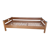
Overview diagram of the product and estimated assembly time of 1.5 hours.

Assembly Instructions

Step 3 & 4 Assembly

Detailed steps for assembling the main frame components, including warnings about bolt protrusion.

Step 5 & 6 Assembly

Instructions for attaching side rails and securing the structure with specific hardware.

Step 7, 8 & 9 Assembly

Steps for adding support elements, securing the bed frame, and preparing for the mattress base.

Step 10 & 11 Assembly

Final assembly steps, including attaching the mattress base support and final tightening.

Important Safety Warnings

Wall Mounting Requirement

Critical instruction to mount the included wall fixings for safety and stability.

Product Care and Maintenance

Cleaning Instructions

Guidance on cleaning surfaces using a damp cloth or commercial furniture care products.

Related product manuals