Do you have a question about the Panasonic CQ-CM140U and is the answer not in the manual?
Installation requires professional knowledge; incorrect installation can damage safety systems, causing injury or death.
Do not connect the power connector until all wiring is completed to prevent unit damage.
Connects to a microphone unit; consult professional installer for microphone unit.
Connects to ACC power source (+12 V DC) for unit operation.
Connects to a clean, bare metallic part of the car chassis for grounding.
Connects to the car battery for continuous +12 V DC power supply.
Connects to an external amplifier for synchronized power on/off.
Connects to a motor antenna; not for switch-actuated power antennas.
Details for connecting front and rear speakers, including polarity and impedance.
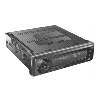
Essential part for mounting the unit into the dashboard.
Used to secure the main unit during installation.
Used for securing the unit to the fire wall.
Tool used to release the unit from the mounting collar.
Connector for the unit's power supply wiring.
Finishes the installation around the unit in the dashboard.
Consult a professional for installation and verify radio operation before final mounting.
Specifies optimal mounting angles and dashboard thickness requirements for installation.
Unit operates exclusively with 12 V battery with negative ground; connect power lead last.
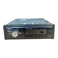
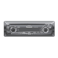
| Type | Car Receiver |
|---|---|
| Brand | Panasonic |
| Model | CQ-CM140U |
| Max Power Output | 50W x 4 |
| RMS Power Output | 22W x 4 |
| Tuner Bands | AM/FM |
| CD Playback | Yes |
| MP3 Playback | Yes |
| WMA Playback | Yes |
| AAC Playback | No |
| USB Port | No |
| Bluetooth | No |
| Display Type | LCD |
| Detachable Face | Yes |
| AUX Input | Yes |
| Channels | 4 |
| Peak Power Output | 50W |
| Preamp Outputs | 2 |
| Preamp Voltage | 2V |