Do you have a question about the Panasonic CS-KE18NB4UW and is the answer not in the manual?
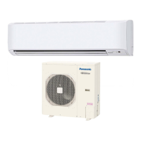
Details the technical specifications and components of DC Inverter Split System Air Conditioners.
Explains the meaning of symbols used for safety precautions in the manual.
Specifies the operating temperature range for cooling mode.
Specifies the operating temperature range for heating mode.
Details the electrical and feature specifications for the indoor and outdoor units.
Provides dimensions and weight for the indoor unit's body and panel.
Provides dimensions and weight for the outdoor unit.
Details cooling specifications for the specified indoor/outdoor unit combination.
Details heating specifications for the specified indoor/outdoor unit combination.
Provides dimensions and weight for the indoor unit's body, panel, and combined unit.
Provides dimensions and weight for the outdoor unit.
Details cooling specifications for the specified indoor/outdoor unit combination at 208V.
Details heating specifications for the specified indoor/outdoor unit combination at 208V.
Lists major component specifications for the indoor unit, including PCB, fan motor, and drain pump.
Details specifications for major components of the indoor unit's body and panel.
Provides specifications for the outdoor unit's control PCB.
Details specifications for the outdoor unit's compressor.
Details specifications for the outdoor unit's control PCB.
Provides specifications for the outdoor unit's compressor.
Shows resistance vs. temperature data for the indoor air temperature sensor.
Provides resistance vs. temperature data for the indoor heat exchanger sensor.
Illustrates dimensional data and connection points for the indoor unit.
Provides dimensional data for the outdoor unit in inches and millimeters.
Details the dimensions of the outdoor unit in inches and millimeters.
Illustrates the refrigerant flow path for cooling and heating cycles.
Presents cooling performance charts based on temperature and fan speed.
Shows heating performance data including pressure and current charts.
Presents cooling performance charts for the specified unit at 230V.
Details heating performance charts for the specified unit at 230V.
Table showing total cooling capacity at various indoor/outdoor conditions.
Presents cooling capacity data for the specified unit combination.
Table detailing total cooling capacity under low ambient conditions.
Provides cooling capacity data for low ambient conditions.
Table shows total heating capacity at various indoor/outdoor conditions.
Details heating capacity for the specified unit combination.
Lists electrical characteristics for cooling and heating operation.
Electrical performance data for 230V operation (cooling and heating).
Electrical performance data for 208V operation (cooling and heating).
Provides the electric wiring diagram for the indoor unit.
Shows the wiring diagram for the outdoor unit CU-KE12NK1.
Illustrates the wiring diagram for the outdoor unit CU-KE18NKU.
Explains how to set the address for multiple remote controllers.
Provides instructions on how to safely disconnect positive connectors.
Details the procedure for connecting positive connectors.
Step-by-step guide to removing the air intake grill of the indoor unit.
Instructions for disconnecting electrical connectors within the control box.
Describes operational modes including Emergency, Auto, Sensor Dry, and PAM control.
Details the color indicators for various operation modes and lamps.
Explains the automatic temperature adjustment for sleep comfort in cooling/dry modes.
Describes automatic temperature adjustment for sleep comfort in heating mode.
Explains how indoor heat exchanger temperature controls compressor load.
Describes how the unit detects and prevents freezing during cooling/dry operation.
Details how operation frequency is controlled to manage compressor discharge temperature.
Outlines the sequence of operations during defrosting mode.
Explains the conditions that trigger defrost detection.
Describes the operation during reverse-cycle defrosting.
Safety precautions and important notes before starting inspection or repair.
Step-by-step guide to perform self-diagnostics using the remote controller.
Table showing indoor unit indications and corresponding diagnosis codes/malfunctions.
Steps to check the indoor unit's operation and voltage.
Steps to check the outdoor unit's operation and voltage.
Procedure for identifying serial communication errors in Condition E01.
Diagnosing a defect in the outdoor unit's PC board.
Diagnosing a defect in the indoor unit's PC board.
Troubleshooting steps for a defect in the indoor unit's PC board.
Troubleshooting steps for a defect in the outdoor unit's PC board.
Diagnosing trouble with the indoor fan motor, including symptoms and measurements.
Procedure to diagnose issues with the outdoor fan motor.
Interpreting diagnostic results for the outdoor fan motor.
Describes noise issues and their causes and corrections.
Explains electromagnetic interference and its mitigation methods.
Procedure for measuring insulation resistance of electrical parts.
Highlights special precautions for servicing units with R410A refrigerant.
Details the characteristics of the new R410A refrigerant.
Specifies flare sizes for R410A and conventional tools.
Provides precautions for handling R410A tubing to prevent dust and moisture.
Lists specialized tools required for R410A servicing.
Lists tools compatible with multiple refrigerants.
Step-by-step procedure for replacing the compressor.
Illustrates cylinder configurations and characteristics for refrigerant charging.
Procedure for detecting refrigerant leaks.
Instructions for recovering refrigerant safely.
Guidance on charging additional refrigerant when tubes are extended.
Caution against using R410A with older R22 units.
Advice on using new tubing when replacing R22 units with R410A.
Operating instructions for specific Panasonic air conditioner models.
General operating instructions for split system air conditioners.
Describes features facilitating automatic operation via remote controller.
Explains automatic switching between cooling and heating modes.
Critical safety instructions related to electrical wiring.
Safety guidelines for safely picking up and moving the units.
Identifies parts of the indoor unit.
Identifies parts of the outdoor unit.
Explains the various symbols displayed on the remote controller.
Describes how to use the fan speed selector button.
Explains how to adjust the flap for airflow direction.
Details the function of the ON/OFF operation button.
Instructions for adjusting temperature settings using the remote.
Instructions for installing batteries in the remote controller.
Guidelines for selecting an optimal location for the remote controller.
Explains automatic operation based on room temperature and settings.
Details how to perform manual operation of the air conditioner.
How to set automatic fan speed based on room temperature.
Instructions for manually adjusting the fan speed.
Night Setback operation in Cooling and DRY modes.
Night Setback operation in Heating mode.
Describes behavior during and after a power failure.
Information on remote controller signals and display malfunctions.
Steps to set the OFF timer for the air conditioner.
Steps to set the ON timer for the air conditioner.
Details the function and procedure for the 1-Hour OFF Timer.
How to use the sweep function for airflow direction.
Instructions for manually setting the airflow direction.
How to operate the unit using the main unit button when the remote is unavailable.
Instructions for cleaning the indoor unit's ceiling panel.
Step-by-step guide on how to remove the air filter for cleaning.
Maintenance steps for the unit after a prolonged idle period.
Common troubleshooting issues and their possible causes and remedies.
Specifies the operational temperature ranges for cooling.
Specifies the operational temperature ranges for heating.
Lists specifications for single-use configurations of indoor and outdoor units.
Details specifications for multiple-use configurations of indoor and outdoor units.
Installation instructions for specific Panasonic air conditioner model combinations.
Crucial information and safety warnings to read before commencing installation.
General information, including tools and accessories required for installation.
Safety guidelines for safely picking up and moving the units.
Site selection criteria and precautions during installation.
Critical safety instructions related to electrical wiring.
Additional safety precautions for servicing and handling refrigerant.
Lists tools that are not supplied but are required for installation.
Details the accessories that are included with the air conditioning unit.
Guidelines for selecting an appropriate installation location for the indoor unit.
Locations to avoid for outdoor unit installation due to heat or humidity.
Recommended practices for outdoor unit installation locations.
Steps for preparing the ceiling for suspending the indoor unit.
Instructions on how to securely suspend the indoor unit.
Ensures correct positioning of the indoor unit relative to the ceiling.
Steps to perform before installing the ceiling panel.
Steps for attaching the corner cover to the ceiling panel.
Instructions for attaching the air-intake grille.
General guidelines and precautions for electrical wiring.
Recommendations for wire length and diameter based on local codes.
Instructions on how to connect wiring to terminals for indoor and outdoor units.
Specific steps for connecting wiring to the indoor unit terminals.
Specific steps for connecting wiring to the outdoor unit terminals.
Details wiring procedures for the outdoor unit installation.
Explains the flaring method for connecting refrigerant tubes.
Step-by-step guide for performing the flaring procedure.
Procedure for air purging using a vacuum pump.
Steps to set the remote controller to Test Run mode.
Initiates the cooling mode test run using the remote controller.
Explains the basic functions of the service valves in different modes.
Procedure for collecting refrigerant gas into the outdoor unit.
Locations to avoid for remote controller installation.
Instructions for mounting the remote controller on a wall.
Procedure for setting the address for multiple remote controllers.
Operating instructions for the CZ-RD515U wired remote controller.
Instructions for operating the wired remote controller.
Describes features facilitating automatic operation via remote controller.
Explains automatic switching between cooling and heating modes.
Critical safety instructions related to electrical wiring.
Safety guidelines for safely picking up and moving the units.
Explains the information displayed on the remote controller.
Describes how to use the fan speed selector button.
Details the function of the ON/OFF operation button.
Explains the function and operation of the 1-Hour OFF Timer.
Explains the various symbols displayed on the remote controller.
Explains automatic operation based on room temperature and settings.
Details how to perform manual operation of the air conditioner.
How to set automatic fan speed based on room temperature.
Instructions for manually adjusting the fan speed.
Night Setback operation in Cooling and DRY modes.
Night Setback operation in Heating mode.
Procedure to set the current time on the remote controller.
Steps to set the OFF timer for the air conditioner.
Details the function and procedure for the 1-Hour OFF Timer.
How to use the sweep function for airflow direction.
Instructions for manually setting the airflow direction.
Installation instructions specifically for the CZ-RD515U remote controller.
Crucial information regarding installation of the wired remote controller.
How to switch between remote and indoor unit sensors.
Steps to set the remote controller to Test Run mode.
Initiates the cooling mode test run using the remote controller.
| Brand | Panasonic |
|---|---|
| Model | CS-KE18NB4UW |
| Category | Air Conditioner |
| Language | English |