26
11 Installation Instruction
11.1. Select The Best Location
11.1.1. Indoor Unit
• Do not install the unit in excessive oil fume area such as
kitchen, workshop and etc.
• There should not be any heat source or steam near the unit.
• There should not be any obstacles blocking the air
circulation.
• A place where air circulation in the room is good.
• A place where drainage can be easily done.
• A place where noise prevention is taken into consideration.
• Do not install the unit near the door way.
• Ensure the spaces indicated by arrows from the wall, ceiling,
fence or other obstacles.
• Recommended installation height for indoor unit shall be at
least 2.5 m.
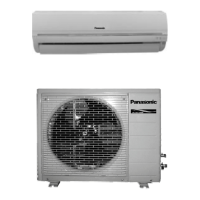
11.1.2. Outdoor Unit
• If an awning is built over the unit to prevent direct sunlight or
rain, be careful that heat radiation from the condenser is not
obstructed.
• There should not be any animal or plant which could be
affected by hot air discharged.
• Keep the spaces indicated by arrows from wall, ceiling,
fence or other obstacles.
• Do not place any obstacles which may cause a short circuit
of the discharged air.
• If piping length is over the [piping length for additional gas],
additional refrigerant should be added as shown in the table.
Example: For C12***
If the unit is installed at 10 m distance, the quantity of additional
refrigerant should be 25 g .... (10-7.5) m x 10 g/m = 25 g
11.1.3. Indoor/Outdoor Unit Installation
Diagram
Model
Horse
Power
(HP)
Piping
size
Std.
Length
(m)
Max.
Ele-
vation
(m)
Min.
Piping
Length
(m)
Max.
Piping
Length
(m)
Addi-
tional
Refri-
gerant
(g/m)
Piping
Length
for
add.
gas
(m)
Gas
Li-
quid
C12***
1.5HP 1/2”
1/4”
7.5
5 3 15 10 7.5
SC/
PC12***
5 3 15 10 7.5
C18***
2.0HP
5/8” 5
20 3 25 20 7.5
SC/
PC18***
20 3 25 20 7.5
C24***
2.5HP
20 3 25 30 7.5
SC/
PC24***
20 3 25 30 7.5