EasyManua.ls Logo

Panasonic CS-YC9MKV User Manual

Panasonic CS-YC9MKV
41 pages
To Next Page IconTo Next Page
Page #1 background imageLoading...
Page #1 background image
© Panasonic Home Appliances Air-Conditioning
(Guangzhou) Co.,Ltd (PHAAG) 2010. All rights
reserved. Unauthorized copying and distribution is a
violation of law.
Order No: PHA-AG1101002C3
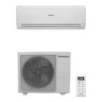
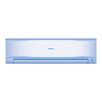
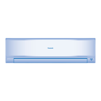
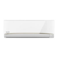
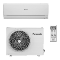
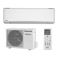
Indoor Unit Outdoor Unit
CS-YC9MKV
CS-YC12MKV
CS-YC12MKV-6
CS-YC9MKV-7
CS-YC12MKV-7
CU-YC9MKV
CU-YC12MKV
CU-YC12MKV-6
CU-YC9MKV-7
CU-YC12MKV-7
TABLE OF CONTENTS
1. Safety Precautions.............................................3
2. Specification.......................................................5
2.1 CS/CU-YC9MKV, CS/CU-YC12MKV...........5
2.2 CS/CU-YC9MKV-7, CS/CU-YC12MKV-7 ....7
2.3 CS/CU-YC12MKV-6.....................................9
3. Location of Controls and Components .........11
3.1 Indoor Unit..................................................11
3.2 Outdoor Unit...............................................11
3.3 Remote Control..........................................11
4. Dimensions.......................................................12
4.1 Indoor Unit..................................................12
4.2 Outdoor Unit...............................................13
5. Refrigeration Cycle Diagram...........................14
6. Block Diagram ..................................................15
7. Wiring Connection Diagram............................16
7.1 Indoor unit ..................................................16
7.2 Outdoor Unit...............................................17
8. Installation Instruction.....................................18
8.1 Select The Best Location ...........................18
8.2 Indoor Unit..................................................19
8.3 Outdoor Unit...............................................22
9. Operation Control.............................................24
9.1 Cooling Operation ......................................24
9.2 Soft Dry Operation......................................25
9.3 Automatic operation ...................................25
9.4 Indoor Fan Speed Control..........................26
9.5 Outdoor Fan Speed Control.......................27
9.6 Vertical Airflow Direction Control................27
WARNING
This service information is designed for experienced repair technicians only and is not designed for use by the general public.
It does not contain warnings or cautions to advise non-technical individuals of potential dangers in attempting to service a product.
Products powered by electricity should be serviced or repaired only by experienced professional technicians. Any attempt to
service or repair the products dealt with in this service information by anyone else could result in serious injury or death.

Questions and Answers:

Panasonic CS-YC9MKV Specifications

General IconGeneral
BrandPanasonic
ModelCS-YC9MKV
CategoryAir Conditioner
LanguageEnglish

Summary

Safety Precautions

General Safety Precautions

Detailed safety guidelines, warnings, and precautions for installation, servicing, and operation.

Specifications

CS/CU-YC9MKV and CS/CU-YC12MKV Specifications

Detailed specifications for the CS/CU-YC9MKV and CS/CU-YC12MKV air conditioner models.

CS/CU-YC9MKV-7 and CS/CU-YC12MKV-7 Specifications

Technical specifications for the CS/CU-YC9MKV-7 and CS/CU-YC12MKV-7 models.

CS/CU-YC12MKV-6 Specifications

Detailed technical specifications for the CS/CU-YC12MKV-6 air conditioner model.

Location of Controls and Components

Indoor Unit Controls and Components

Diagram and labels identifying controls and components on the indoor unit.

Outdoor Unit Controls and Components

Diagram showing the air inlets and outlets of the outdoor unit.

Remote Control Functions

Description and labeling of buttons and display on the air conditioner remote control.

Dimensions

Indoor Unit Dimensions

Visual representation and measurements of the indoor unit's physical size from various angles.

Outdoor Unit Dimensions

Diagrams illustrating the top, front, and side views with dimensions for the outdoor unit.

Refrigeration Cycle Diagram

Block Diagram

Wiring Connection Diagrams

Indoor Unit Wiring Diagram

Schematic showing electrical connections within the indoor unit, including motors, sensors, and control boards.

Outdoor Unit Wiring Diagram

Wiring diagram for the outdoor unit, illustrating connections for the compressor, fan motor, and capacitors.

Installation Instructions

Selecting the Best Installation Location

Guidelines for choosing optimal locations for both indoor and outdoor units to ensure performance and safety.

Indoor Unit Installation Location Guidelines

Criteria for selecting the best location for the indoor unit, considering heat sources, obstacles, and drainage.

Outdoor Unit Installation Location Guidelines

Criteria for selecting the best location for the outdoor unit, considering airflow, heat discharge, and surroundings.

Indoor Unit Installation Procedures

Detailed steps for installing the indoor unit, including fixing the installation plate and drilling holes.

Fixing the Indoor Unit Installation Plate

Instructions on mounting the installation plate, ensuring correct alignment and securing it to the wall.

Indoor Unit Installation Steps

Step-by-step guide for mounting the indoor unit onto the installation plate and connecting piping and cables.

Connecting Indoor Unit Cables

Instructions for connecting the power supply and communication cables between the indoor and outdoor units.

Cutting and Flaring Piping

Procedure for cutting copper pipes and flaring them correctly for secure refrigerant connections.

Outdoor Unit Installation

Mounting the Outdoor Unit

Steps for securely fixing the outdoor unit to its mounting base, considering environmental factors like wind and earthquakes.

Connecting Refrigerant Piping

Detailed instructions for connecting the refrigerant pipes to both indoor and outdoor units, including torque specifications.

Evacuation Procedure

Steps for evacuating air and moisture from the refrigerant system using a vacuum pump.

Operation Control

Cooling Operation Mode

Explanation of the cooling operation, including temperature settings and compressor control logic.

Cooling Operation Time Graph

Graphical representation of cooling operation parameters, showing intake air, set temperature, and compressor status over time.

Soft Dry Operation Mode

Description of the Soft Dry operation for dehumidification and gentle cooling, including its operational characteristics.

Soft Dry Operation Time Graph

Graphical representation of Soft Dry operation, detailing intake air, evaporator temperature, and fan speed.

Automatic Operation Mode

Explanation of the automatic operation mode, which determines settings based on intake air temperature and user preferences.

Indoor Fan Speed Control

Methods for controlling indoor fan speed, including manual and automatic settings.

Automatic Indoor Fan Speed Control

Explanation of how the fan speed adjusts automatically during cooling and soft dry operations.

Vertical Airflow Direction Control

How to adjust the vertical louvers using the remote control and their behavior when operation stops.

Timer Control Functions

Details on setting and canceling ON/OFF timers, including specific behavior for cooling, soft dry, and auto modes.

Protection Controls

Restart Control (Time Delay Safety)

Description of the compressor's 3-minute delay for cooling and 6-minute delay for soft dry operations to balance refrigerant pressure.

Anti-Freezing Control

Mechanism to prevent evaporator freezing by stopping the compressor when evaporator temperature drops below 2°C.

Dew Prevention Control

Control that activates to prevent dew formation at the indoor unit discharge by adjusting the air vane and fan operation.

Servicing Modes

Auto Off/On Button Functions

Explanation of the Auto Off/On button for activating auto operation, test run, and controlling remote control receiving sound.

Remote Control Buttons and Functions

Description of remote control buttons for mode selection, temperature adjustment, fan speed, and air swing.

Troubleshooting Guide

Refrigeration Cycle Troubleshooting

Diagnosing malfunctions by measuring air temperatures, electric current, and gas side pressure.

AC Condition vs. Pressure & Electric Current

Table showing relationships between AC conditions, pressure, and electric current for diagnosing faults.

Compressor Malfunction Diagnosis

Methods for diagnosing compressor issues such as insufficient compression and locked compressor conditions.

Disassembly and Assembly Instructions

Front Panel Removal Procedure

Step-by-step guide on how to safely remove the front panel of the indoor unit.

Front Grille Removal Procedure

Instructions for removing the front grille by disengaging caps and unscrewing fasteners.

Discharge Grille Removal Procedure

Steps for detaching the discharge grille from the indoor unit, including separating the drain hose.

Cross Flow Fan Removal Procedure

Detailed steps for removing the cross-flow fan, including loosening screws and removing the bearing.

Exploded View and Parts List

Indoor Unit Exploded View and Parts List

Diagram showing all components of the indoor unit and a list of their part numbers and descriptions.

Outdoor Unit Exploded View and Parts List

Exploded view diagram and comprehensive parts list for the outdoor unit, detailing each component.

Related product manuals