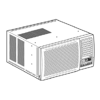
1 Air inlet louvre 4 Air filter (behind the
front intake grille)
2 Cabinet 5 Front intake
grille
3 Power cord 6 Front grille
7 Vertical airflow direction vane
(Airflow direction adjustment up-
down).
The vertical airflow direction vane
is controlled by rotating the
horizontal vane forward or backward.
2
AIR CONDITIONER INSTALLATION
3
PART IDENTIFICATION
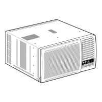
REMOVAL OF FRONT GRILLE
1
Remove the front intake grille.
Pull up the front intake grille
about 90° and slide it slightly
to the left to unhook the tabs.
2
Remove the air filter.
Tilt up and pull out
the air filter by the
holder.
3
Remove the front grille.
aa
aa
a
At bottom right side of the front grille, press inward on cabinet near the power cord, and pull
the grille outward to the right until right tab releases.
bb
bb
b
At the bottom left side, push inward on cabinet and pull the grille outward to the left to release
the left tab.
Do not pull the bottom edge toward you more than 3 inches to prevent the two top tabs from
damage.
cc
cc
c
Slide the front grille upwards to free the two top tabs from slots at the top of the cabinet.
HOW TO ATTACH THE DRAIN PAN (OPTIONAL)
Maximum
13/32”
Condensed water
This air conditioner employs a “Slinger-Up System” which is designed to splash the condensed
water on the condenser coil for maximum cooling efficiency, thus producing a splashing sound.
If the splashing sound annoys you, you can provide an outside drainage by using the following
procedure which may, however, cause a small loss of performance.
Note: The cabinet should be installed tilted slightly lower to the rear for necessary condensate
drainage. (Max. 13/32”)
Condensed water drainage
1
Remove the rubber plug and slide the chassis out from
the cabinet.
Remove the
rubber plug
O
F
F
/
O
N
O
PE
RATIO
N
T
E
M
P
/
T
I
M
E
R
C
O
O
L
F
A
N
H
I
G
H
L
O
W
M
O
D
E
F
A
N
S
P
E
E
D
S
E
T
T
I
M
E
R
S
E
T
/
C
A
N
C
E
L
A
I
R
S
W
I
N
G
J
E
T
M
O
D
E
h
r
¡
C
W
ire
le
s
s
R
e
m
o
t
e
C
o
n
t
r
o
l
2
Install the optional drain pan (part no. CWH40175).
Screws
INTERNAL VIEW
Drain pan (optional)
Install the drain pan at the right
corner of the cabinet using 2
screws (part no. CWG86C733).
3
Connect a drain hose (optional).
Fit the drain hose to the drain pan.
Underside view with drain
pan and hose in place.
Drain hose
(not included)
4
Slide the chassis back into the
cabinet.
Reinstall the cabinet screws.
Secure the cabinet to chassis by
using screws.
Note
The drain pan (part no.
CWH40175) can be obtained
from nearest servicentre.
MAIN UNIT
O
F
F
/
O
N
O
P
E
R
A
T
I
O
N
T
E
M
P
/
T
I
M
E
R
C
O
O
L
F
A
N
H
I
G
H
L
O
W
M
O
D
E
F
A
N
S
P
E
E
D
S
E
T
T
I
M
E
R
S
E
T
/
C
A
N
C
E
L
A
I
R
S
W
I
N
G
J
E
T
M
O
D
E
h
r
¡
C
W
i
r
e
l
e
s
s
R
e
m
o
t
e
C
o
n
t
r
o
l
9 Touch control panel

 Loading...