8-ENGLISH
Projection relationships
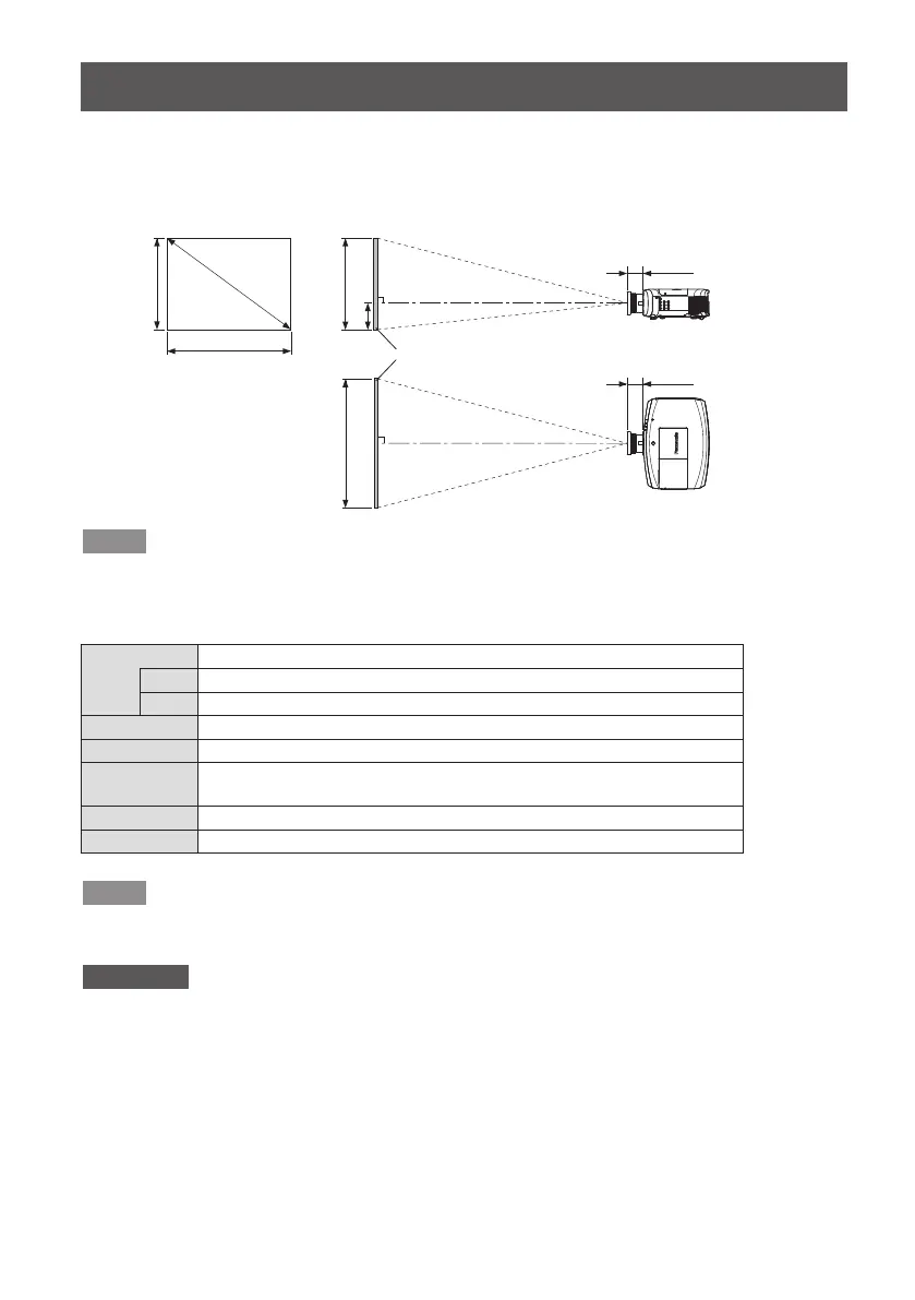
The dimensional relationship between the screen and the projector is shown below.
■
Dimensional relationship diagram
L (LW/LT)
L (LW/LT)
SW SH
H
SW
SD
L1: 0.095 m (3-3/4")
L1: 0.095 m (3-3/4")
Screen
Projected image
Note
z
This diagram assumes that the size and position of the projected image will be adjusted so
thattheimagellstheentirescreen.
z
This illustration is not drawn to scale.
L Projection distance
LW Minimum distance
LT Maximum distance
L1 Lens protrusion dimension
SH Image height
H Distance from the lens center to the lower edge of the projected
image
SW Image width
SD Projected image size
Note
z
The illustrations of projectors in this manual are for informational purposes only and do not
representaspecicprojectormodel.Congurationsmayvarywiththemodel.
Attention
z
To prevent blocking of the intake and exhaust vents, maintain clearances from walls and
objects of at least
1 000 mm (3'3") for the exhaust vent and at least 500 mm (1'8") for the intake vent.
z
Avoid setting up in places which are subject to sudden temperature changes, such as near
an air conditioner or lighting equipment (studio lamps, etc.).
 Loading...