Flourescent
lamp/Ampoule flourescente
Night
lamp/
Veilleuse
ON
ON
Main control circuit/
Circuit de commande principal
Blue/Bleu
Red/Rouge
Red/Rouge
Yellow/Jaune
White/Blanc
White/Blanc
Live/Sous
tension
Live/Sous
tension
Neutral/
Neutre
()
VENT.
()
N.LIGHT
()
LIGHT
Black/Noir
Black/Noir
DC-
Motor/
DC-
Moteur
AC120V
60Hz/
120V CA
60Hz
AC120V
60Hz/
120V CA
60Hz
(Power supply/
Alimentation
electrique)
Air volume/
Debit d air
Adjustment
switch/
Commutateur
de reglage
Lighting unit/Appareil d eclairage
Electronic
ballast/
Ballast
Red/RougeRed/Rouge
Red/RougeRed/Rouge
Black/Noir
Black/Noir
White/Blanc
White/Blanc
Blue/Bleu
Blue/Bleu
Blue/Bleu
Blue/Bleu
White/
Blanc
White/
Blanc
Green/Vert
Black/
Noir
Black/
Noir
Black/
Noir
Switch box/Boite
de commutation
Switch box/Boite
de commutation
Red/Rouge
White/Blanc
Live/Sous
tension
Neutral/
Neutre
Black/Noir
Delay time/
La minuterie
AC120V
60Hz/
120V CA
60Hz
(Earth ground/
Mise a la terre)
Wiring diagram/Schema de connexions
ON
Hi
Fan body/Boite du ventilateur
Junction box/Boite de raccordement
(Power supply/
Alimentation
electrique)
White/
Blanc
Black/
Noir
Green/
Vert
Rouge
Red/
Rouge
Red/
FV-08VKSL3
Model No.
AC120V 60Hz 0.33A Fan 0.53A Light
() ( )
3. Suitable for use with motor Model 13KML3M20
1. Not for use in cooking area-See installation instructions
2. Type IC-Inherently Protected
2. Type IC-Protection Intrinseque
1. Non destine a la zone de cuisson-Voir instructions d installation
3. Approprie pour une utilisation avec le moteur
Modele 13KML3M20
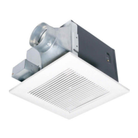
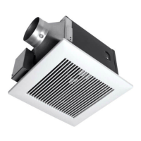
Ventilating Fan
Ventilateur
Made in China /Fabrique en Chine
Panasonic Corporation ofNorth America
3
FV-08VKSL3
E
23
25
28
24
26
27
G
A
44
43
42
45
47
46
48
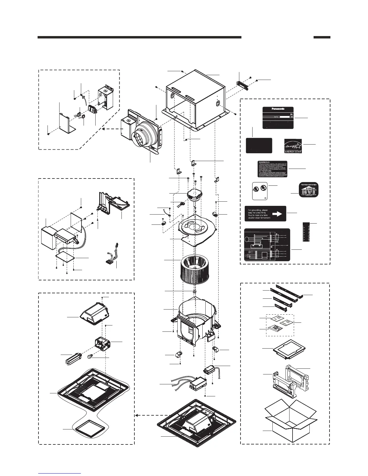
Main Packing Materials
38
39
40
41
Main Labels
29
31
32
35
33
34
37
Main PCB Section
mm
Inch
60
2
50
40
30
20
10
1
_
2
2
1
1
_
2
1
1
_
2
(Stuck On Frame Assy)
1
2
B
(3pcs)
A
(2pcs)
8
(3pcs)
D
(4pcs)
9
10
C
12
13
E
12
15
16
17
B
(3pcs)
18
19
E
F
(4pcs)
F
(4pcs)
20
21
22
E
(2pcs)
30
36
(2pcs)
(5pcs)
A
14
12
E
(2pcs)
3
4
6
5
7
A
Details Of Wiring Section
11
49
(49)
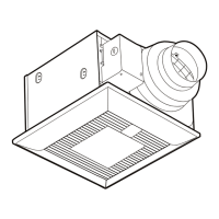
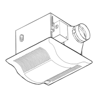
2.Parts Identification
Main Body Section
C
CAUTION:
2.1m(7feet)above the floor.
To reduce the risk of injury to persons,install fan at least
ATTENTION:
Afin de reduire les risques de blessures corporelles,
Installer le ventilateur a au moins 2,1m(7 pieds)du sol.
FAN
8B68
US
LISTEN
A375682G8
C
50
Grille Assy Section