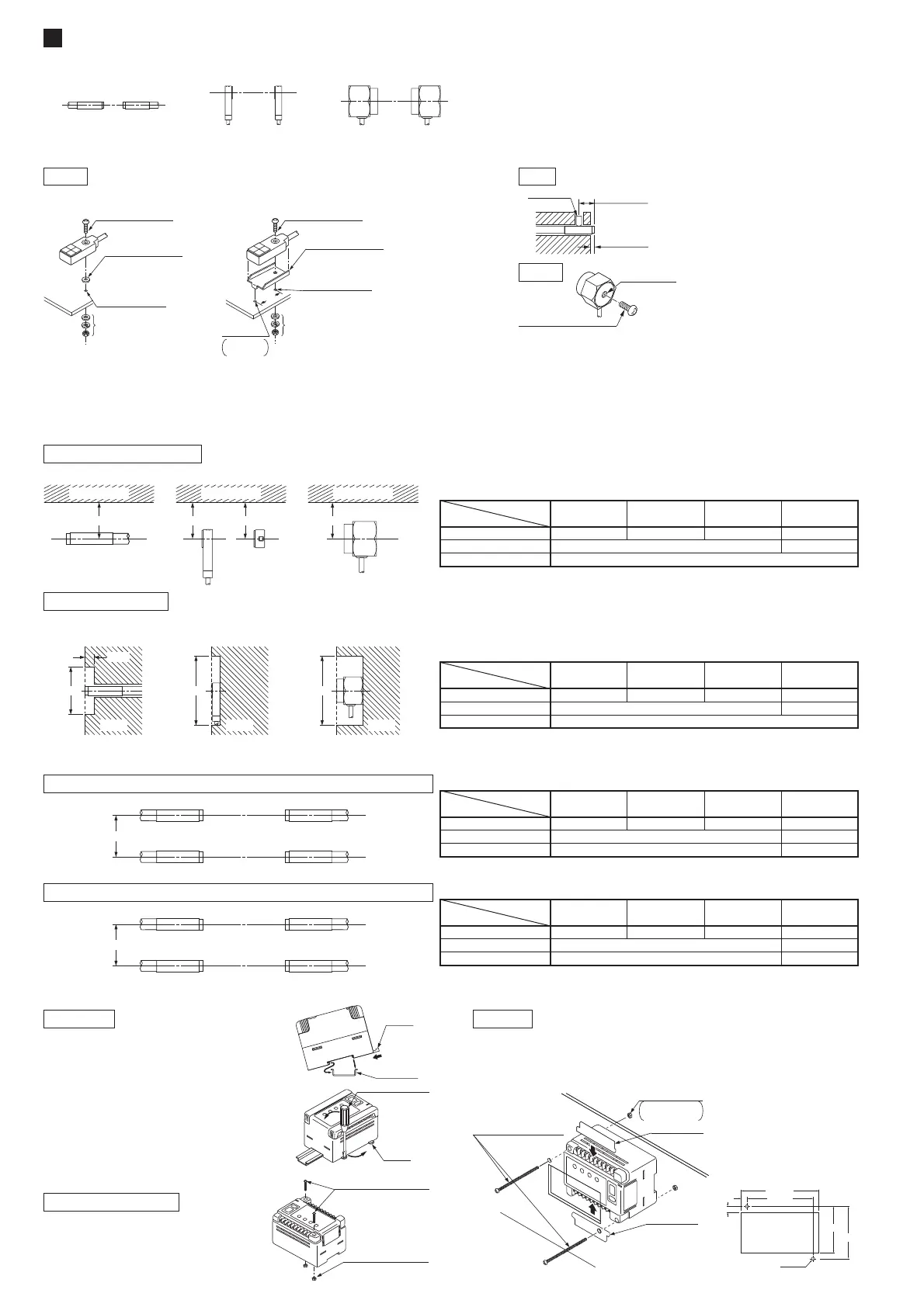
MOUNTING
3
٨
Placing of sensor heads
Make the sender and receiver face each other and align their sensing center line.
٨
Distance from nearby metals
As metals near the sensor head may affect the sensing performance, pay attention to the following points.
The sensor head must be separated from nearby metal by a minimum distance as specified in the table below.
Keep a distance from any magnet or a device generating magnetic field. It may degrade the detectability.
The sensing performance may be affected if the sensor is completely embedded in a metal. Keep a minimum clearance between the sensor
head and the metal as specified in the table below.
٨ Mounting of sensor heads
GD-10
Use a set screw (M3 or less), and
the tightening torque should be
0.12N㨯m or less.
The tightening torque should be
11.2N㨯m or less.
The tightening torque should be 0.5N㨯m or less.
To mount the sensor head with a nut, the thru-hole should be Ǿ3.4mm.
(The mounting board must be 2.3mm, or less, thick.)
٨
Interference prevention
When two or more sensor heads are mounted in parallel, keep a minimum separation distance as specified below to avoid interference.
٨ Mounting of controller
Ԙ
ԙ
With the stopper pressed in the
direction of the arrow (it locks), fit
the front portion of the mounting
section of the amplifier on the
35mm width DIN rail.
Press and fit the rear portion of
the mounting section on the
35mm width DIN rail.
To remove, insert a flathead
screwdriver into the stopper and
pull out.
Use two M4 pan head screws
10mm, or more, long. The tight-
ening torque should be 1.2N㨯m
or less.
To mount the controller on a panel, use two M4 pan head screws
70mm, or more, long and the tightening torque should be 1.2N㨯m
or less. If your mounting panel is metallic, insert the attached insu-
lation plates at the terminals.
On panel
M4 (length 70mm or more)
pan head screws
(Please arrange separately.)
Insulation plate
Insulation plate
Nuts
Please arrange
separately.
96
r0.2
8.5
+0.5
0
113
+0.5
0
76
r0.2
67.5
+0.5
0
8.5
0.5
-
0
2-Ǿ4.5
*Mounting hole dimensions (Unit: mm)
D
Sender Receiver
Sender Receiver
C
Sender Receiver
Receiver Sender
In case the sender and another sensor's receiver are placed adjacently
On DIN rail
On board with screws
Note: The value in the brackets is for GD-20.
Dimension C (in case of iron)
220mm
630mm
Model No.
Setting distance (Note)
5mm 10mm 20 (35) mm 30 (70) mm
60mmGD-3 80mm
㧙㧙
160mmGD-10
370mmGD-20
In case the respective senders and receivers are placed adjacently
Note: The value in the brackets is for GD-20.
Dimension D (in case of iron)
250mm
700mm
Model No.
Setting distance (Note)
5mm 10mm 2035mm 3070mm
30mmGD-3 50mm
㧙㧙
200mmGD-10
450mmGD-20
Stopper
35mm width
DIN rail
Ԙ
ԙ
Flathead screwdriver
Stopper
(Please arrange separately.)
M4 (length 10mm or more)
pan head screws
(Please arrange separately.)
Nuts
GD-3
GD-20
Influence of nearby metal
Embedding in metal
If mounting using nut
and washers
(Accessory for GD-10)
M3 (length 12mm)
pan head screw
(Accessory for GD-10)
M30.5mm tapped
hole, 10mm or more
deep, or Ǿ3.4mm
thru-hole
Anti-slip rubber
washer
(Accessory for GD-10)
<Fixing at one point> <Fixing at two points>
4mm or more
2mm or more
Set screw
(M3 or less)
M8 mounting
hole, 6mm deep
M8 screw
(Please arrange separately.)
A
Nearby metal
GD-3
Nearby metal
A A
GD-10
Nearby metal
A
GD-20
Dimension A (in case of iron)
Model No.
Setting distance
5mm 10mm 30mm 70mm
15mmGD-3 20mm
㧙㧙
100mmGD-10
100mmGD-20
㧙
Dimension B (in case of iron)
Model No.
Setting distance
5mm 10mm 30mm 70mm
Ǿ15mmGD-3 Ǿ20mm
㧙㧙
Ǿ100mmGD-10
Ǿ300mmGD-20
㧙
B
Metal
5mm
GD-3
B
Metal
GD-10
B
Metal
GD-20
16
If mounting using nut
and washers
(Accessory for GD-10)
M3 (length 12mm)
pan head screw
(Accessory for GD-10)
Mounting bracket
(Accessory for GD-10)
M30.5mm tapped
hole, 10mm or more
deep, or Ǿ3.4mm
thru-hole
Ǿ2.5mm
hole
3mm or
more deep
 Loading...