Do you have a question about the Panasonic GD Series and is the answer not in the manual?
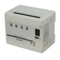
Protective cover for accessing the product's interface and controls.
Indicates when the unit is powered on, confirming operational status.
Key used to specify channel selection method: Panel, Lock, or External inputs.
Indicates the unit's status: lights up under normal conditions, flashes on error.
Indicates the current sensing mode: Green for normal, Yellow for precise.
Lights up when the OUT-1 output is OFF, indicating no detection.
Lights up when the OUT-2 output is OFF, indicating no detection.
Seven LEDs showing the sensing level, indicating object thickness or quantity.
Shows the present channel (1 to 8) and blinks during SET mode.
Used to select channels when the selection method is set to PANEL.
Sets the two-sheet threshold level, which is the higher sensitivity level.
Sets the one-sheet threshold level, which is the lower sensitivity level.
Calibrates the zero level under no-sheet condition.
Switches between RUN mode (detection) and SET mode (setup).
Switches between NORM. mode (no timer) and OFD. mode (50ms delay timer).
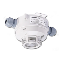
Instructions for attaching sensor heads, including fixing points and torque.
Specifies minimum distances to metal for optimal sensing performance.
Guidelines for clearances when sensor heads are partially embedded in metal.
Minimum separation distances to prevent interference between sensor heads.
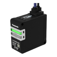
Methods for mounting the controller unit on a DIN rail or panel.
Procedure for setting sensitivity using the device's control panel keys.
Method for setting sensitivity using external input signals.
Describes normal and precise sensing modes, automatically selected by object characteristics.
Enables shifting the two-sheet threshold level for stable detection.
Details the 50ms delay timer for output signals, useful for slow response devices.
Explains how the unit diagnoses itself, indicating errors via indicators and display.
Locks all keys on the operation panel when activated by the channel shift key.
Configuration of RS-232C communication parameters using DIP switches.
Details of write and read commands for data communication via RS-232C.
Technical specifications for sensor heads, including sensing range and materials.
Technical specifications for controllers, including supply voltage and output types.
| Category | Security Sensors |
|---|---|
| Brand | Panasonic |
| Detection Method | Passive Infrared |
| Detection Angle | 110 degrees |
| Humidity Range | 95% RH or less (no condensation) |