EasyManua.ls Logo

Panasonic KX-T2373MXW - User Manual

Panasonic KX-T2373MXW
35 pages
To Next Page IconTo Next Page
Loading...
© 2001 Kyushu Matsushita Electric Co., Ltd. All
rights reserved. Unauthorized copying and
distribution is a violation of law.
KX-T2373MXW
Integrated Telephone System
White Version
(for Asia, Middle Near East and other areas)
Telephone Equipment
ORDER NO. KM40108848C3
Question and Answer IconNeed help?

Do you have a question about the Panasonic KX-T2373MXW and is the answer not in the manual?

Panasonic KX-T2373MXW Specifications

General IconGeneral
BrandPanasonic
ModelKX-T2373MXW
CategoryTelephone
LanguageEnglish

Summary

SPECIFICATIONS

1 LOCATION OF CONTROLS

2 CONNECTION

2.1. Connecting the Handset;Telephone Line Cord

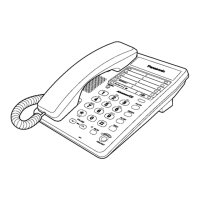
Connects the handset and telephone line cord to the unit.

2.2. Connecting a Communication Device

Connects a communication device to the DATA jack.

3 SETTINGS

3.1. Selecting the Dialing Mode

Configures the phone for Tone (DTMF) or Pulse dialing.

3.2. Selecting the Ringer Volume

Adjusts the ringer volume to High, Low, or Off.

4 SPECIAL FEATURES

4.1. FLASH Button

Enables special PBX features like call transfer and call waiting.

4.2. Selecting the Flash Time

Sets the flash time for PBX features like call transfer.

4.3. Setting the Pin Code

Sets a 4-digit PIN code for dial lock and call restriction.

4.4. Dial Lock

Prevents unauthorized calls except for programmed emergency numbers.

4.5. Call Restriction

Prevents dialing numbers with specified leading digits.

4.6. How to Release the Establishment of Dial Lock

Resets or changes the dial lock password.

5 DISASSEMBLY INSTRUCTIONS

6 HOW TO REPLACE FLAT PACKAGE IC

6.1. Preparation

Lists required tools and materials for IC replacement.

6.2. Procedure

Step-by-step guide for replacing a flat package IC.

6.3. Modification Procedure of Bridge

Instructions for modifying bridged connections during IC replacement.

7 CPU DATA

7.1. IC801

Detailed pin description and data for IC801.

7.2. Speakerphone IC Data

8 TERMINAL GUIDE OF ICS TRANSISTORS AND DIODES

9 BLOCK DIAGRAM

10 BLOCK DIAGRAM (IC 1)

10.1. Communication ICs

Describes the function of communication ICs.

11 CIRCUIT OPERATION

11.1. Bell Detector Circuit

Explains how the bell signal is detected and outputted.

11.2. Line Interface

Details the circuit operation for line connection and signal flow.

11.3. MODULE BLOCK DIAGRAM

11.3.1. Speakerphone Circuit

Explains the function and operation of the speakerphone circuit.

11.3.2. Telephone Line Interface

Describes the telephone line interface circuit operation.

11.3.3. Tone Detect

11.3.4. Inializing Circuit

12 TROUBLE SHOOTING GUIDE

12.1. Service Hints

Provides quick checks and cures for common symptoms.

12.2. Pulse Dialing Problems

Troubleshooting guide for issues with pulse dialing.

12.3. Tone Dialing Problems (Hnadset)

12.4. No Ringing Sound When Ring Signal is Input.

13 CABINET AND ELECTRICAL PARTS LOCATION

14 ACCESSORY AND PACKING MATERIALS

15 REPLACEMENT PARTS LIST

15.1. Base Unit

Lists replacement parts for the base unit.

15.1.1. CABINET AND ELECTRICAL PARTS

Lists cabinet and electrical components for replacement.

15.1.2. MAIN P.C.BOARD PARTS

Lists replacement parts for the main PC board.

16 FOR SCHEMATIC DIAGRAM (SCHEMATIC DIAGRAM)

16.1. ΜΕΜΟ

A section for notes and remarks related to schematic diagrams.

17 SCHEMATIC DIAGRAM

Related product manuals