
T
Teresa CarterJul 28, 2025
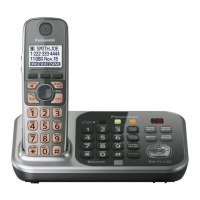
How to fix not recording on Panasonic Phone?
- AannnicholsJul 28, 2025
To address recording issues on your Panasonic Phone, try adjusting the Auto disconnect activation time and Vox level.
How to fix not recording on Panasonic Phone?
To address recording issues on your Panasonic Phone, try adjusting the Auto disconnect activation time and Vox level.
Why does my Panasonic Phone say 'NG'?
If your Panasonic Phone displays 'NG', it indicates an issue with the Bluetooth Function. To resolve this, check the BT Communication.
Warning for experienced repair technicians; not for general public.
Highlights critical safety components marked with A for replacement.
Information on using lead-free solder (PbF) and its properties.
Precautions for service technicians during repair work to prevent hazards.
Precautions to prevent malfunctions caused by static electricity.
Caution regarding battery replacement, explosion risk, and recycling.
Handling precautions for lead-free solder, including melting point differences.
Overview of the circuit configuration for TG774x series phones.
Details on BBIC functions like voice recording, DTMF, Caller ID.
Operation of Flash Memory IC502 for main program data.
Operation of Flash Memory IC601 for voice signal data.
Operation of EEPROM IC611 for settings data.
Operation of Bluetooth Unit IC721 for communication.
Operation of power supply and reset circuits in the base unit.
Block diagram illustrating the components of the handset.
Overview of ICs and interfaces within the handset.
Operation of power supply and reset circuits within the handset.
Procedures for entering engineering mode on the base unit.
Procedure to clear user settings and initialize the handset.
Flowchart for diagnosing and resolving product issues.
Procedure to identify defective parts in the RF section.
Step-by-step instructions for disassembling the base unit.
List of necessary equipment for measurements and adjustments.
Method for setting up the JIG and connecting it to the base unit.
Bottom view of the base unit showing adjustment points.
Bottom view of the charger unit showing adjustment points.
Component view of the handset showing adjustment points.
Procedure for downloading data to the base unit after component replacement.
Procedure for replacing Leadless Leadframe Package (LLP) ICs.
Terminal identification for base unit ICs, transistors, and diodes.
Terminal identification for handset ICs, transistors, and diodes.
Terminal identification for charger ICs, transistors, and diodes.
Schematic diagram for the base unit's main circuit.
Component layout of the base unit main PCB.
Exploded view and parts list for base unit cabinets and electrical components.
List of accessories and packing materials for KX-TG7741S.
List of replacement parts for the base unit main P.C. board.
| Type | Cordless Phone |
|---|---|
| Frequency | 1.9 GHz |
| Handsets Included | 1 |
| DECT 6.0 Technology | Yes |
| Caller ID | Yes |
| Talking Caller ID | Yes |
| Call Block | Yes |
| Answering System | Yes |
| Answering Machine | Yes |
| Speakerphone | Yes |
| Keypad on Base | Yes |
| Ringer ID | Yes |
| Power Backup | Yes |
| Range | Up to 1000 feet |
| Battery Life | Up to 10 hours talk time |
| Call Waiting | Yes |
| Intercom | Yes |
| Display | LCD |
| Power Source | AC Adapter |
| Expandable Handsets | Up to 6 |