J
Jennifer RoseNov 4, 2025
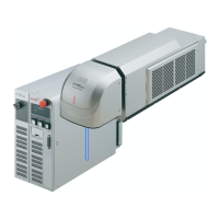
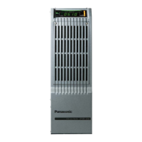
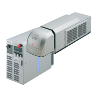
What to do if Panasonic LP-RH Measuring Instruments system does not start?
- MmoralesreneeNov 4, 2025
If your Panasonic Measuring Instruments system isn't starting, there are several potential causes: * The power cable might not be properly connected. Ensure the power supply cable is securely connected. * The key switch may not be turned on. Turn on the key switch. * There might be an issue with the power supply itself. Check the power supply. * In the case of the LP-GS series, the fuse might be blown. Replace the fuse, referring to the 'Setup/Maintenance Guide' for the correct procedure. * For LP-RC, LP-RH, LP-RF, LP-RV, and LP-ZV series, the circuit protector could be off. Turn on the circuit protector, following the instructions in the 'Setup/Maintenance Guide'. * There could be a fault in the internal circuit. Check the external power supply with the laser marker removed. ...