EasyManua.ls Logo

Panasonic LP-V10U User Manual

Panasonic LP-V10U
180 pages
To Next Page IconTo Next Page
Page #1 background imageLoading...
Page #1 background image
2018.7
panasonic.net/id/pidsx/global
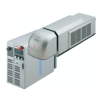
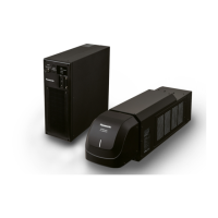
Laser Marker
External Control Manual
LP-400 series
LP-V series
LP-W series
ME-LP400V-EX-6 No. 9000-0062-17V

Table of Contents

Question and Answer IconNeed help?

Do you have a question about the Panasonic LP-V10U and is the answer not in the manual?

Panasonic LP-V10U Specifications

General IconGeneral
BrandPanasonic
ModelLP-V10U
CategoryMeasuring Instruments
LanguageEnglish

Summary

Cautions in Handling

DANGER Safety Precautions

Critical safety precautions for avoiding serious injury or death.

WARNING Safety Precautions

Safety precautions to prevent serious injury or death.

1-1 Laser Marker Operation Methods

Manual Screen Operation

Describes how to operate the laser marker using its screen interface.

External Device Control (Remote Mode)

Explains controlling the marker remotely via I/O or communication.

1-1-1 Test and Run Mode Operation Procedures

Operation Flow Chart

Visual guide for performing test marking and run mode operations.

1-1-2 Test and Run Mode Operation Details

Test Marking and Run Mode Procedures

Step-by-step guides for test marking and run mode operations.

1-2 Operation by External Devices

I/O and Serial Communication for Remote Operation

Controlling the marker via I/O or serial communication in remote mode.

1-2-2 External Control Operation Procedures

External Control Operation Example (PLC)

Illustrates an operation procedure when controlling the marker via external devices like PLC.

1-3 Settings Before External Control

Setting Flow for External Control

Outlines the sequence of settings required before initiating external control.

1-3-1 DIP Switch Settings

DIP Switch No. 2: Control Method Selection

Details the function of DIP switch No. 2 for selecting control methods.

DIP Switch Settings (Continued)

DIP Switch No. 5: Remote Mode Setting

Explains the function of DIP switch No. 5 for setting remote mode.

DIP Switch No. 6: Remote Mode State at Power-On

Details the function of DIP switch No. 6 for selecting remote mode state at power-on.

1-3-2 Communication Condition Settings

I/O Signal Output Conditions

How to configure output conditions for I/O signals.

I/O Connector Signal Operations

How to select operations for I/O connector signals.

Serial Communication Conditions

Serial Communication Conditions (RS-232C/Ethernet)

Setting communication parameters for Ethernet or RS-232C.

1-3-3 Shifting to Remote Mode

Remote Mode via Controller Switch

How to shift to remote mode using the controller's front switch.

Remote Mode via REMOTE IN Signal

How to shift to remote mode using the REMOTE IN I/O terminal signal.

2 Control by I/O

2-1 I/O Interface Specifications

I/O Terminal Block and Connector Descriptions

Describes the I/O terminal block and connector for interface specifications.

2-1-1 I/O Terminal Block Details

NPN and PNP Type I/O Terminal Blocks

Specifications for NPN and PNP type I/O terminal blocks.

2-1-3 I/O Terminal Block Signals and Details

Signals in the I/O Terminal Block

Details the signals and their functions for the I/O terminal block.

Input Signal Operation on I/O Terminal Block

Input Signal Details (A1-A4)

Details of input signals A1 (+12V OUT), A2 (IN COM.), A3 (REMOTE IN), A4 (TRIG. IN).

Input Signal Details (Continued)

Encoder, Laser Control, and Stop Signals (A5-A12)

Details for encoder, laser control, stop, alarm, and unused signals.

Output Signal Operation on I/O Terminal Block

Output Signal Details (B1-B3)

Details for output signals B1 (0V OUT), B2 (OUT COM.), B3 (REMOTE OUT).

Output Signal Details (Continued)

Output Signals for Status, Warnings, and Alarms (B4-B10)

Details for output signals indicating ready status, marking, warnings, and alarms.

Emergency Stop Output and Input Signals (B11-B12)

Details for emergency stop output common and input signals.

2-1-4 Signals and Details of I/O Connector

Signals in the I/O Connector

Lists and details all signals available on the I/O connector.

Input Signal Operation on I/O Connector

Common Input/Output and SET IN Signals (Terminal 1-2)

Details for common terminals and the SET IN signal.

Data Input Signals (Terminal 3-18)

Details for D0-D15 input signals for various functions.

Input Signal Operations (Continued)

File Number and Counter Value Correction Input

How to input file numbers and counter values for correction.

Counter Reset and Rank/External Offset Data Input

How to input counter reset numbers and rank/offset data.

SELECT, TIME HOLD, and RESERVE Inputs (20-29)

Details for SELECT, TIME HOLD, and RESERVE input signals.

Output Signal Operation on I/O Connector

RESERVE and Counter End Outputs (30-35)

Details on RESERVE terminals and counter end output signals.

SET OK Output (36)

Describes the SET OK output signal indicating successful setting completion.

Output Signal Operations (Continued)

Output/Input Common Terminal (37)

Details for the OUT COM./IN COM. terminal.

2-2 Input/Output Ratings

Input Rating and Circuit

Electrical ratings and circuit diagrams for input signals.

2-2-2 Output Rating and Output Circuit

Output Rating and Circuit

Electrical ratings and circuit diagrams for output signals.

2-3 Connecting I/O Terminal Block

NPN Models Connection Sample

Example wiring for NPN models for independent operation.

Connecting Sample for PNP Models

PNP Models Connection Sample

Example wiring for PNP models for independent operation.

2-3-2 Connecting Samples with External Devices

Connecting Sample for PNP Models (Controlled by External Devices)

2-4 Timing Charts

Timing Charts (Continued)

Safety Function Operation Overview

3 Control by Serial Communication (RS-232/Ethernet)

3-1 Preparation for Command Control

RS-232C Interface Details

RS-232C Communication Conditions

3-1-2 Ethernet

Ethernet Connection to External Devices

3-2 Command Reception Conditions

3-3 Connection Check

3-4 Control Sample

Control Sample 1-1: Changing Marking Characters

Control Sample 1-2: Changing Marking Characters Per Marking

Control Sample 2: Changing Marking Files

3-5 Communication Data Format

Response Data Format

Response Data Format (Continued)

Readout Data Format

3-5-3 Communication Sequence

3-6 Communication Command List

Operation Control Commands

Lists commands for controlling operations like pumping, shutter, and status requests.

Command List Categories (Continued)

3-7 Command Descriptions

LSR Command Description (Laser Pumping)

SHT Command Description (Shutter Control)

STS Command Description (Status Request)

MST Command Description (Marking Status Transmission)

MRK Command Description (Marking Trigger)

GID Command Description (Guide Laser Control)

FNO Command Description (File Change - No. Specified)

FNN Command Description (File Change - Comment Specified)

FOR Command Description (File Overwriting Registration)

FRG Command Description (File Registration)

FNM Command Description (File Name)

MCS Command Description (Marking Character String - ASCII)

STR Command Description (Marking Character String - Shift-JIS)

Character String Setting Methods

SIN Command Description (Serial Data Input)

Serial Data Marking Timing Chart

RKC Command Description (Rank Condition)

RKS Command Description (Rank Character String)

CNT Command Description (Counter Condition)

CTR Command Description (Counter Reset)

LMT Command Description (Expiry Date/Time Condition)

LTC Command Description (Lot Condition)

LTS Command Description (Lot Character String)

BCS Command Description (Bar Code Marking Data - ASCII)

BBS Command Description (Bar Code Marking Data - ASCII)

BRS Command Description (Bar Code Marking Data - Shift-JIS)

BRF Command Description (Bar Code Marking Condition)

Bar Code Parameters

Laser and Speed Adjustment Parameters

BRV Command Description (Human Readable Text)

BRP Command Description (2D Code Pattern)

CDF Command Description (Logo File)

CDC Command Description (VEC Logo Conditions)

CDD Command Description (DXF Logo Condition)

FIG Command Description (Processing Element)

Processing Element Parameters

Processing Element Parameters (Continued)

LAY Command Description (Processing Condition)

PRD Command Description (Arbitrary Point Radiation Coordinate and Time)

PRF Command Description (Arbitrary Point Radiation Condition)

ALC Command Description (General Condition)

SPC Command Description (Character Condition - Shortened Form)

STC Command Description (Character Condition)

OFC Command Description (External Offset Condition)

OFS Command Description (External Offset Coordinates)

SRC Command Description (Step & Repeat Condition)

SRA Command Description (Step & Repeat Fine Adjustment)

LPW Command Description (Laser Power)

SSP Command Description (Scan Speed)

MPL Command Description (Laser Pulse Cycle)

CWL Command Description (CW Pulse Cycle/Duty)

MPL Command Description (CO2 Laser Frequency)

WDC Command Description (Line Width/Marking Pitch)

WTC Command Description (Marking Quality Adjustment)

TRG Command Description (Trigger Condition)

DLY Command Description (Delay)

INT Command Description (Marking Interval)

MWT Command Description (Flying Object Wait)

LSP Command Description (Line Speed)

ENC Command Description (Encoder Signal)

SPT Command Description (Laser Check Radiation)

PWR Command Description (Power Check)

ECR Command Description (Error Code Readout)

ECR Command Description (Error Code Readout)

Detailed description of the ECR command for reading error codes.

YMD Command Description (Year/Month/Date/Time)

ERA Command Description (Era Year)

WKM Command Description (Week Setting)

ENV Command Description (I/O Environment)

Troubleshooting

Start-up Troubles

Lists common start-up problems and their solutions.

Laser Pumping Troubles

Lists common issues related to laser pumping and their resolutions.

Display Troubles

Lists issues related to the display and control panel, and their causes/measures.

Marking Troubles

Lists common problems encountered during the marking process and their solutions.

Marking Quality Troubles

Lists issues affecting marking quality and provides remedies.

Marking Disorder Troubles

Lists causes and measures for character disorder or unreadable markings.

Moving Objects Marking Troubles

Lists problems related to marking moving objects and their solutions.

External Control Troubles

Lists issues with external control signals and serial communication.

Serial Communication Control Failures

Details failures in serial communication control and their causes.

Command Not Accepted (NAK Response)

Explains why commands might not be accepted by the marker (NAK response).

Error Indication

Alarm Errors and Release Methods

Describes alarm errors and procedures for releasing them.

Laser and System Errors (E230-E312)

Details various laser, system, and connection errors and their solutions.

Combination, Memory, and Lasing Errors (E320-E700)

Details errors related to unit combination, memory, lasing, and general system errors.

Warning Errors

Warning Errors and Release Methods

Describes warning errors and procedures for releasing them.

Marking Area, Character, Memory, and Flying Object Errors (E606-E623)

Errors related to marking area, characters, memory, and flying object operations.

Function, File Conversion, Measurement, and Code Errors (E640-E902)

Errors related to function usage, file conversion, measurement, and code creation.

2D Code and Barcode Errors (E903-E914)

Errors related to 2D code patterns, barcode creation, and dimensions.

Character Code Table

Related product manuals