Do you have a question about the Panasonic NN-A574SBBPQ and is the answer not in the manual?
Explains how output power is controlled by the inverter and digital programmer circuit via pulse width modulation.
Details auto weight defrost and auto weight cook functions, including categories and cooking times.
Emphasizes the necessity of proper grounding for safe operation and repair of the microwave oven.
Highlights dangers of high voltage and temperatures on the inverter power supply and heat sink.
Provides instructions for replacing components, emphasizing power cord removal and safety precautions.
Specifies replacing short switch, primary latch switch, and relay RY1 when the 10A fuse blows.
Warns against inserting objects into oven cavity openings to prevent microwave leakage.
Details checks after repair, including screw tightness, electrical connections, and microwave leakage.
Advises caution when handling the unit due to potentially sharp edges during unpacking and installation.
Step-by-step guide for removing and replacing the magnetron, including safety notes and microwave leakage prevention.
Procedure for removing the inverter circuit board, including discharging capacitors and handling high voltage components.
Instructions for removing the DPC assembly, escutcheon base, and membrane assembly, with static precautions.
Details on removing low voltage transformer and power relays, including soldering precautions.
Procedure for removing the fan motor assembly, including fan blade detachment.
Step-by-step guide for removing and replacing the microwave oven door, including screen and key mechanisms.
Instructions for removing the turntable motor, including breaking off the motor cover and disconnecting wires.
Procedure for removing pulley belt, heater hood, pulley A, thermistor, and fan cover.
Tests continuity of primary/secondary latch switches and power relay B using an ohm meter with door open/closed.
Procedure to test the short switch continuity with the oven door open and closed.
Checks magnetron filament continuity and resistance for open or shorted conditions.
Checks continuity of switch terminals on the DPC AU by tapping pads and measuring ribbon cable resistance.
Caution against repairing the inverter power supply; replacement as a unit is recommended.
Warns against measuring high voltage circuits in the inverter or magnetron and suggests troubleshooting references.
Guides installation and adjustment of door hook assembly, latch switches, and continuity checks.
Outlines a simple method to test magnetron output by measuring water temperature rise after heating.
Provides a table of symptoms, causes, and corrections for 'no operation' issues like dead oven or no key input.
Lists causes and corrections for a '10A fuse blown' symptom, including switch and inverter checks.
Addresses issues like low microwave output, buzzing noise, turntable not rotating, and oven stopping during cooking.
Describes a test for inverter shutdown issues by monitoring input voltage and using self-test mode.
Presents an alternative test for inverter circuit issues by monitoring input current and using self-test mode.
Troubleshooting guide for DPC issues like no display, dead oven, no key input, no beep, and power relay faults.
Provides resistance readings for checking diodes, transistors, and digital transistors using a multimeter.
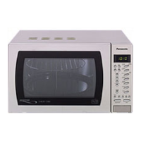
| Brand | Panasonic |
|---|---|
| Model | NN-A574SBBPQ |
| Category | Microwave Oven |
| Language | English |