Do you have a question about the Panasonic NV-F55EG and is the answer not in the manual?
Procedure for identifying faulty chip components on a PCB using heat.
Step-by-step guide for replacing chip components like resistors and capacitors.
Methods for safely removing surface-mount integrated circuits (Flat-ICs).
Details on the dual-mode loading stop system and its response times.
Capability to play NTSC tapes on PAL TVs and dub NTSC 4.43.
Convenient automatic playback functions like Repeat, Memory, and Sleep Playback.
Automatic removal of dust and particles from video heads for consistent quality.
Explanation of indicators shown on the multi-function display for VTR status.
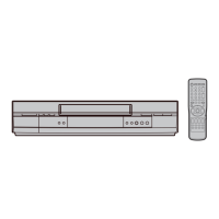
Functions of various buttons and switches on the front panel.
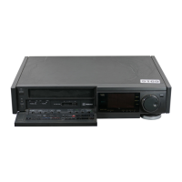
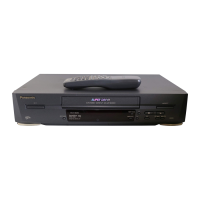
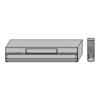
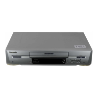
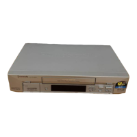
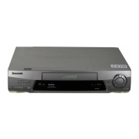
Identification and numbering of all controls and components on the front panel.
Functions of major buttons like Power, Eject, and Remote Receiver.
Explanation of Bilingual, Stereo, and MESECAM indicator lights.
Selector for editing operations or ordinary VTR use, and noise filtering.
Ensures accurate Remaining Tape Time indication for different tape lengths.
Functions of playback, rewind, fast forward, and OTR buttons.
Enables insert editing, affecting audio and video tracks.
Step-by-step guide for performing insert editing on tape.
How to play back tapes with insert editing and select audio tracks.
Functions of clock, tracking, AFC/VPS, channel selection, and other operational buttons.
Functions of audio output, PAL/MESECAM, VTR/TV, timer, and cancel buttons.
Diagram and description of all rear panel connectors and sockets for input/output.
Detailed identification and functions of remote control buttons.
Buttons for PAL/MESECAM, Mode Select, Programme Select, and Auto Play.
Functions of Reset, Tape Remain, FF/Cue, Play, Still, and Transmit buttons.
Visual guide showing the sequence of steps for VTR disassembly.
Detailed instructions for removing the top and bottom panels, including screw locations.
Steps for removing the front panel, involving screws, tabs, and connectors.
Instructions for removing the Timer and Operation circuit boards.
Procedures for removing the main circuit board and power supply unit.
Steps to remove the cassette compartment, including screws and cables.
Instructions for removing the cleaner arm unit, involving springs and locking parts.
Method for adjusting tape interchangeability, requiring a cut jumper wire.
Identification of test points and controls on the main circuit board.
Test points and controls specific to the Hi-Fi audio pack.
Test points and controls for the luminance and chrominance pack.
Test points and controls for the head amplifier circuit board.
Test points and controls for the timer circuit board.
List of essential test equipment required for electrical adjustments.
Initial setup and selector settings required before starting adjustments.
Instructions on interpreting adjustment procedures, including test points and waveforms.
Procedure for adjusting the PG shifter for correct head switching and sync.
Method for adjusting slow tracking to minimize noise bars on the monitor.
Procedure to balance the Y-NR signal by minimizing amplitude at a specific pin.
Procedure to adjust the artificial PAL AFC for proper operation.
Steps to adjust recording current for optimal sync and color signals.
Procedure for adjusting video frequency response to meet specific dB levels.
Procedure to minimize chrominance amplitude for proper color signal.
Adjusting the Hi-Fi E-E signal level to specific dB values.
Adjusting carrier frequencies for NTSC and PAL modes using a frequency counter.
Diagram showing how all circuit boards (C.B.A.s) are interconnected.
Exploded view of the VTR chassis, showing assembly of major mechanical components.
List of replacement circuit board assemblies with part numbers.
List of replacement capacitors with part numbers and values.
List of replacement transistors with part numbers.
List of replacement resistors with part numbers and values.