Do you have a question about the Panasonic NV-GS180EG and is the answer not in the manual?
Details on power requirements and consumption.
Tape type, recording modes, playback time.
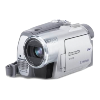
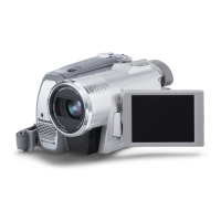
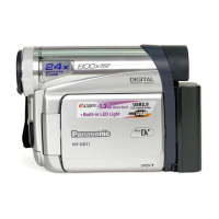
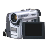
Image sensor, lens, zoom, monitor details.
Output levels, recording systems.
Memory card usage, still image specs.
Purpose and scope of the service manual.
Guidelines and precautions for working with lead-free solder.
Important safety precautions and warnings.
Handling of AC cord, fuse replacement, and plug safety.
Visual guide for unit disassembly for service.
Detailed steps for disassembling various camcorder parts.
Specific disassembly steps for the mechanical unit.
Procedures for EEPROM data during PCB replacement.
Information on required extension cables for servicing.
Diagrams showing connector pinouts on main and sub PCBs.
Overview of the TATSUJIN PC-Adjustment system.
Steps for connecting and preparing the camcorder for adjustment.
Instructions for using the PC-EVR adjustment software.
Table of adjustments needed based on replaced parts.
Lists items for mechanical adjustment and confirmation methods.
Step-by-step guide for performing mechanical adjustments.
How errors are displayed and the reset procedure.
Steps to enter the service menu and initiate diagnostics.
Reference table showing waveform characteristics for test points.
High-level block diagram of the camcorder's circuitry.
Diagram showing how different PCBs are interconnected.
Schematic for the Electronic Viewfinder (EVF) PCB.
Schematic for the CCD flex card assembly.
Schematic for the front PCB.
Component layout for the EVF printed circuit board.
Component layout for the LCD detection PCB.
Component layout for the front printed circuit board.
Component layout for the monitor printed circuit board.
Exploded views of the camera's frame and casing parts.
Exploded view of the camcorder's LCD screen assembly.
Exploded view of the camcorder's camera lens components.
Exploded view of the VCR mechanism parts.
Exploded view of included packing materials and accessories.
Lists of replacement parts for frame and casing.
Replacement parts for LCD assembly and camera lens unit.
List of replacement parts for the VCR mechanism.
List of electronic components and their part numbers.
| Type | Camcorder |
|---|---|
| Optical Zoom | 30x |
| Digital Zoom | 1000x |
| Video Resolution | 720 x 576 |
| Display Type | LCD |
| Microphone | Built-in |
| Battery Type | Lithium Ion |
| Recording Format | Mini DV |
| Sensor | CCD |
| Viewfinder | Color |
| Image Stabilization | Electronic |
| LCD Screen Size | 2.7 inches |
| Optical Sensor Resolution | 800, 000 pixels |
| Focus Adjustment | Auto, Manual |
| Minimum Illumination | 1 Lux |
| Display Size | 2.7 inches |
| Connector Type | USB, AV out |
| Supported Flash Memory | SD Card |
| Zoom | 1000x Digital |
| Recording Media | MiniDV |
| Weight (without battery) | 410g |