Do you have a question about the Panasonic NV-HS1000 and is the answer not in the manual?
Provides essential information for servicing the K-Mechanism and related operations.
Details the "E9" error indication for serial data transmission issues.
Explains the Service Information Display (SID) for troubleshooting and diagnostic purposes.
Explains the different service modes for diagnostics and checks.
Details the service information numbers indicating malfunctions.
Illustrates the timing chart for mode switches and system control signals.
Covers technical aspects like editing controller function and AI recording.
Explains the program editing capabilities via edit cable connection.
Describes the AI function for optimizing picture quality during recording.
Details the serial data transmission protocol between microprocessors.
Provides guidance on safe and proper operation, including connections and precautions.
Outlines essential safety and environmental precautions for VTR operation.
Covers the fundamental connections required for recording and playback via TV.
Details connecting the VTR to a TV using a 21-pin Scart terminal.
Explains the connection using an S-Video socket for higher picture quality.
Describes how to connect a Pay TV decoder for recording.
Guides on how to tune the television to the VTR signal.
Explains the procedure to set the VTR's internal clock.
Details the process of saving TV broadcast channels into the VTR.
Guides on configuring the remote for ShowView programming.
Explains how to set up the remote controller to operate TVs from various manufacturers.
Guides for initial setup using on-screen display menus.
Describes optional functions like VITC for advanced editing.
Covers operations related to playing back recorded tapes.
Details how to perform recording directly from a TV program.
Explains the process of scheduling recordings using the timer function.
Guides on programming recordings using ShowView numbers.
Covers connections and setup required for video editing functions.
Details various manual and program editing capabilities.
Provides step-by-step instructions for manual video editing tasks.
Explains how to perform automatic programming and assemble editing.
Covers additional editing functions like confirmation and cancellation.
Describes editing procedures without an edit cable.
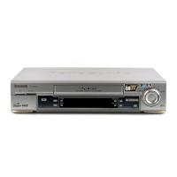
Identifies and explains the function of unit controls and external connectors.
Explains advanced functions and controls of the unit.
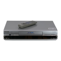
Details the operation and functions of the infra-red remote controller.
Provides procedures for adjusting and calibrating unit components.
Outlines the steps for disassembling the unit for servicing purposes.
Details procedures for mechanical adjustments and unit replacement.
Refers to K Mechanical Chassis manual for specific mechanism disassembly.
Refers to K Mechanical Chassis manual for specific mechanism assembly.
Provides detailed steps for electrical adjustments and tests.
Lists the necessary test equipment for electrical adjustments.
Specifies the selector settings required before performing adjustments.
Explains how to interpret adjustment procedures and diagrams.
Details the procedure for adjusting the PG shifter.
Outlines the steps for adjusting slow tracking.
Describes the procedure for adjusting reverse slow tracking.
Details the process for adjusting auto tracking gain.
Explains the adjustment for artificial PAL free run.
Covers the procedure for adjusting the recording current.
Details the adjustment for VHS frequency response.
Outlines the procedure for adjusting RF peak frequency.
Describes the adjustment for S-VHS frequency response.
Details the adjustment for VHS playback level.
Outlines the procedure for adjusting S-VHS playback level.
Explains the adjustment for the YNR circuit.
Details the adjustment for chrominance recursive settings.
Outlines the procedure for adjusting 1H delay gain.
Describes the adjustment for the TBC noise gate.
Details the adjustment for TBC sync level.
Outlines the procedure for adjusting TBC white balance.
Explains the adjustment for TBC R-Y level.
Details the adjustment for TBC digital chrominance level.
Outlines the procedure for TBC playback level adjustment.
Explains the adjustment for the AGC level.
Covers adjustments related to the audio circuits.
Covers the adjustment for bias current in the audio section.
Details the Hi-Fi E-E level adjustment procedure.
Explains the adjustment for carrier frequency.
Outlines the procedure for deviation adjustment.
Describes the adjustment for FM B.P.F. settings.
Covers adjustments related to the timer circuits.
Details the adjustment for the timer reference clock.
Outlines the adjustment for the level meter sensitivity.
Explains the adjustment for the character generator VCO.
Lists common abbreviations used in the block diagrams and manual.
Illustrates the block diagram for editing functions.
Shows the system control and servo block diagram of the unit.
Presents the block diagram for luminance and chrominance circuits.
Details the Time Base Corrector (TBC) block diagram.
Illustrates the block diagram for the Hi-Fi audio system.
Provides the schematic for the power supply section.
Shows the component layout for the power circuit board.
Details the schematic for system control and servo sections.
Presents the schematic for audio sections on main and sub packs.
Provides the schematic for luminance and chrominance sections.
Shows the component layout of the main circuit board.
Provides the schematic diagram for the capstan drive pack.
Shows the component layout for the capstan drive circuit board.
Provides the schematic diagram for the luminance/chrominance pack.
Shows the component layout for the luminance/chrominance circuit board.
Shows the component layout for the sub luminance/chrominance circuit board.
Provides the schematic diagram for the sub luminance/chrominance pack.
Details the schematic for the Time Base Corrector (TBC) circuit.
Shows the component layout for the TBC circuit board.
Shows the component layout for the Head Amplifier circuit board.
Provides the schematic diagram for the Head Amplifier circuit.
Details the schematic for the Hi-Fi audio pack.
Shows the component layout for the Hi-Fi audio circuit board.
Provides the schematic diagram for the input/output pack.
Shows the component layout for the input/output circuit board.
Details the schematic for the NICAM decoder pack.
Shows the component layout for the NICAM decoder circuit board.
Provides the schematic diagram for the decoder pack.
Shows the component layout for the decoder circuit board.
Details the schematic for the TV demodulator pack.
Shows the component layout for the TV demodulator circuit board.
Provides the schematic diagram for the timer and VR circuits.
Shows the component layout for the timer and VR circuit boards.
Details the schematic for the TV demodulator pack.
Shows the component layout for the TV demodulator circuit board.
Provides exploded views and a list of mechanical replacement parts.
Lists mechanical parts for the first chassis section.
Lists mechanical parts for the second chassis section.
Details the mechanical parts related to the unit's casing.
Lists mechanical parts associated with packaging and shipping.
Provides an exploded view and parts list for the remote controller.
Lists electrical components for replacement.