EasyManua.ls Logo

Panasonic NV-RZ1EG User Manual

Panasonic NV-RZ1EG
83 pages
To Next Page IconTo Next Page
Page #1 background imageLoading...
Page #1 background image
ORDER NO. VMD0001001C8
VHS-C Movie
NV-RZ1EG / NV-RZ1B / NV-RZ1E / NV-RZ1EN / NV-RZ1ENC /
NV-RZ1A / NV-RZ2EG / NV-RZ2B / NV-RZ2EN
CZ-MECHANISM
SPECIFICATIONS
1
Question and Answer IconNeed help?

Do you have a question about the Panasonic NV-RZ1EG and is the answer not in the manual?

Panasonic NV-RZ1EG Specifications

General IconGeneral
Camcorder Media TypeMiniDV
Optical Zoom10x
Digital Zoom500 x
LCD Screen Size2.5 inches
FocusAuto/Manual
Viewfindercolor
Audio Recording FormatPCM
BatteryLithium-ion
Recording FormatDV
Image SensorCCD
InterfaceIEEE 1394 (FireWire)
Weight480g (without battery)

Summary

Specifications

Introduction

1.1. Introduction to Service Manual

Provides technical information for service personnel to understand and service the model.

Service Cautions

2.1. EEPROM Data for Spare Parts

Details EEPROM data replacement procedures for spare parts of camera/main C.B.A.

2.2. Service Extension Cables

Lists required extension cables for convenient service connections.

Parts Numbering System

Extension Cables Parts Description

Describes the numbering system and meaning for flexible cables used as extension cables.

Service Information

3.1. Service Information Display

Explains the SERVICE INFORMATION DISPLAY function for quick troubleshooting.

Error Code Display

Service Modes

3.3. Service Mode 3

Details how to check error codes after undesirable conditions occur.

3.4. Inserting the Button-Type Battery

Instructions for inserting the button-type battery for the internal clock.

Adjustment Procedures

5.1. Disassembly Procedures

Provides a flowchart for disassembly procedures, detailing steps for removing units.

Disassembly Procedures - Key Units

Disassembly Procedures - Frame and Units

5.2. Disassembly Procedures of Lens Unit

Block Diagrams

Block Diagrams - Camera, System, Video

Presents block diagrams for camera, system control, servo, power, and video sections.

Schematic Diagrams

Schematics - Camera, Lens, Audio, Video

Provides schematics for camera, lens drive, audio, video, and system control circuits.

Circuit Board Assemblies

Circuit Board Assemblies - Camera, EVF, Mic

Details assemblies for Camera/Main C.B.A., EVF C.B.A., CCD Flex Card, and Mic Unit.

Exploded Views

Exploded Views - VTR Mechanism Sections

Exploded views of the VTR mechanism, covering sections 1, 2, and 3.

Exploded Views - Camera Lens and Frame/Casing

Exploded Views - Packing Parts & Accessories

Replacement Parts List

Parts List - VTR Mechanism Sections

Lists replacement parts for VTR mechanism sections 1, 2, and 3.

Parts List - Camera Lens, Frame & Casing

Parts List - Packing & Accessories

12.7. Electric Parts List

Electric Parts List - Capacitors

Detailed list of capacitors, including part numbers, descriptions, and quantities.

Electric Parts List - Diodes, Filters, Connectors

Electric Parts List - ICs and Coils

Electric Parts List - Transistors and Chip Beads

Electric Parts List - Resistors (R)

Electric Parts List - Resistors (cont.) and Fuses/Oscillators

Electric Parts List - ICs, Diodes, Switches

Electric Parts List - Various Components

Schematics

Schematic - Power and System Control

Schematic diagram showing power distribution and system control circuitry.

Schematic - CCD Drive and DSP

Schematic - Video Path and Motor Drives

Schematic - CCD Flex. Card C.B.A.

Schematic - IC291 (CCD) and Amplifier

Schematic - VEP28271A (EVF C.B.A.) Layouts

Schematic - IC801 (EVF Drive)

Schematic - IC6801 (Remote Control Sensor)

Schematic - System Control Microprocessor

Schematic - VEP23504B (Main C.B.A.) Component Side

Schematic - VEP23504B (Main C.B.A.) Foil Side

Mic Unit PCB Layout

Schematic - Audio Main Signal Path

Schematic - Power and Motor Control

Schematic - Power and Lens Drive Control

Schematic - Motor Drives (Capstan, Cylinder)

Schematic - System Control Microprocessor

Schematic - VTR Operation Logic

Schematic - Input/Output Signals

Waveform Table

Waveforms for IC6008-IC6010

Displays waveforms for IC6008, IC6009, and IC6010 under various modes.

Waveforms for Q6001-Q6014

Waveforms for QR6001-QR6050

Schematic - Video Signal Path

Schematic - Logic and Motor Control

Schematic - Audio Signal Path

Controls and Components

Camera Controls and Features

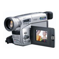
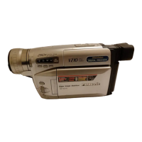
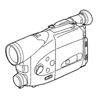
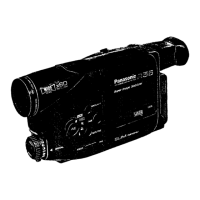
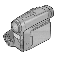
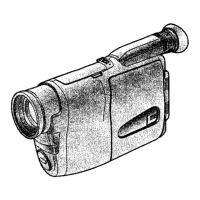
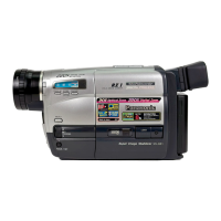
Identifies camera controls, body features, and accessory connections.

Charging the Battery

Using the Menus

Setting the Date and Time

Recording with Time/Date Overlay

Recording in Dark Places

Manual White Balance Adjustment

Colour Temperature and White Balance Adjustment

Optional Accessories

ABBREVIATIONS

ABBREVIATIONS (cont.)

Continuation of the list of abbreviations used in the manual.

Waveform Table

Key Waveform Examples

Illustrates typical waveforms for various ICs and transistors under different modes.

Waveforms for IC1001, Q1001-Q1062

Schematic - Audio and Video Signal Paths

Schematic - Signal Processing and Control

Related product manuals