1-10
P2531
P2552
P3501
Head Amp C.B.A.
Shaft of Main
Cam Gear
Extension Cable -2
Extension Cable -1
Full Erase
Head Connector
Mode Select SW. Ass'y
See 3 Clip-on
Wires connection
Alignment
Projection
EJECT
Position
Mode Select SW.
on Mode Select
SW. Ass'y
SERVICE
Rotate
TP6021
TP6022
TP6023
Main C.B.A.
(Component Side)
3 Clip-on Wires connection
Mode Select SW.
Red
Orange
Yellow
Extension Cable -1:
Extension Cable -2:
Mode Select SW. Ass'y:
Full Erase Head Connector on the
Mechanism Chassis Unit ~ P4001
on the Main C.B.A.
Note: No change in performance if
pins are reversed.
P3501 on the Head Amp C.B.A.
~ P3003 on the Main C.B.A.
a) 3 Clip-on Wires ~ Test Points
on the Main C.B.A.
Red Wire ~ TP6021
Orange Wire ~ TP6022
Yellow Wire ~ TP6023
b) 8 Pin Connector ~ P6002 on the
Main C.B.A.
c) 14 Pin Connector ~ P6201 on the
Main C.B.A.
d) Set Mode Select SW. on the Mode
Select SW. Ass'y to EJECT position
and install onto Mechanism Chassis
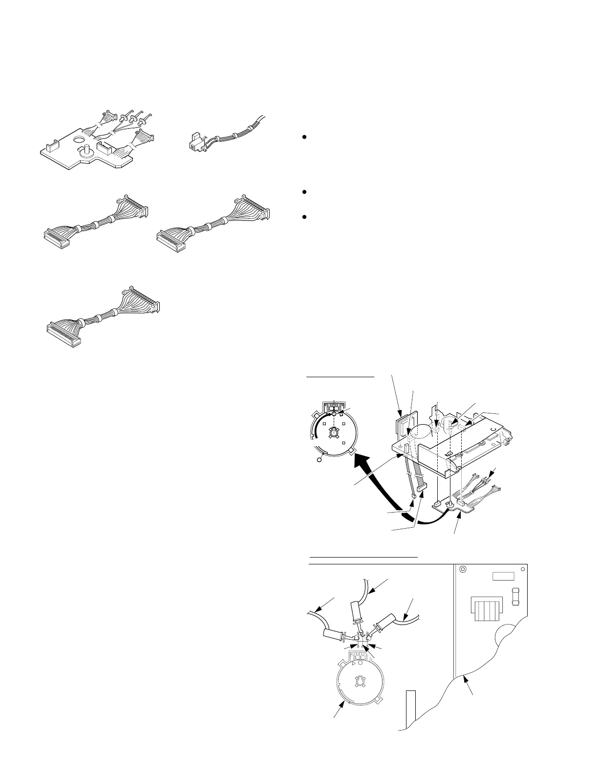
Extension Cable -2
(VUVS0005)
for 2 Head Model
Mode Select SW. Ass'y
(VUVS0001)
8 pin
3 clip-on
wires
14 pin
2 pin
12 pin
15 pin
20 pin
Extension Cable -2
(VUVS0004)
for 4 Head Model
Extension Cable -2
(VUVS0003)
for Hi-Fi Model
Extension Cable -1
(VUVS0002)
How to place the unit into Service Position with
Extension Cables
1. Remove Rear Cover, VCR Unit, (Stereo Amp C.B.A.:
Model K), Top Shield Plate Ass'y, Mechanism Chassis,
and Cassette Up Ass'y.
2. Connect the Extension Cables as follows:
Fig. 2-5
Extension Cable Kit (VUZS0002)
Fig. 2-4
Note:
3 types of Extension Cable -2 are included in this kit. Since
there is a difference in the number of P3501 Head Amp C.B.A.
pins between 2 Head, 4 Head, and Hi-Fi models, be sure to use
the proper cable.
 Loading...