EasyManua.ls Logo

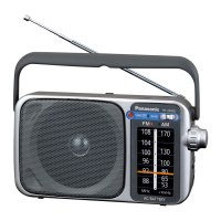
Panasonic RF-B45

Panasonic RF-B45
15 pages
To Next Page IconTo Next Page
To Previous Page IconTo Previous Page
Loading...
JOO
|
Il
mG
JErl
ni
@
Band
indicators
Received
band
appears.
@
Multi
indicator
RF-B45
RF-B45
@
DISASSEMBLY
INSTRUCTIONS
®
Standby
indicator
Appears
while
the
standby
function
is
oper-
ating.
Or
flashes
while
the
standby
time
is
being
set.
@
Hold
indicator
@
Sleep
indicator
Appears
while
the
sleep
timer
is
operating.
@
Tuning
indicator
Appears
when
a
signa!
is
received.
The
bar
display
indicates
the
receiving
signal
strength.
Memory
indicator
Appears
when
memory
tuning
is
done,
or
flashes
when
you
memorize
a
frequency.
@
Memory
channel/empty
indicator
indicates
the
memory
channel
when
the
frequency
is
received
by
memory
tuning.
How
to
change
the
step
of
MW
(10
kHz<—>
9
kHz)
This
unit
can
be
used
on
MW
10
kHz
step
area,
but
in
case
of
MW
9
kHz
step
area,
operate
as
follows.
Before
operation,
turn
off
the
radio.
1
Press
the
AM
key
of
the
band
select
keys.
“MW”
indication
flashes
for
10
seconds.
{
a
oy
!
|
‘a
|
Leo
atesn
2
During
flashing,
press
the
number
“9"
key.
“9"
appears
and
flashes
for
10
seconds
and
returns
clock
time
display.
—__——
g
:
{
|
i
i
m
ACCESSORIES
SW
extemal
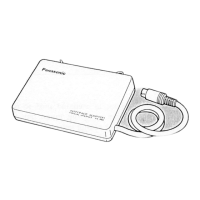
antenna...
1
pc.
XEH1A1-AB
RFC0013
Earphone............
+
pe.
3
White
flashing,
press
the
enter
key.
009
"
flashes
on
the
display.
nnn
,
Suu
{
When
you
want
to
set
MW
10
kHz
step,
press
the
number
“0”
key
instead
of
the
number
“9”
key.
"10"
flashes
on
the
display.
NOTE:
When
you
change
the
MW
step,
all
the
memo-
rized
stations
will
be
cleared.
m
NOTE
FOR
SERVICE
eAbout
hold
switch
Before
checking
the
operation
problems
and
adjustments,
be
sure
to
release
the
hold
state.
Fon
Setting
the
hold
key
to
“HOLD”
position
will
hold
the
present
condition,
and
reject
the
operation
of
the
front
panei
buttons.
This
is
useful
to
prevent
unexpected
operation.
©
(The
hold
indicator
wili
appear
on
the
display.)
i
Before
operating
the
front
pane!
button,
be
sure
ial
!
to
release
the
hold
condition.
(The
hold
indicator
will
disappear.)
BATTERY
SERVICE
LIFE
RE.
“AA”
size
battenes
Approx.
14.5
hours
of
FM
posibon
(EtAJ)
Approx.
13
hours
of
LW
and
MW
position
(EIAJ)
Approx.
14
hours
of
SW
position
(EIAJ)
The
above
battery
service
life
is
measured
according
to
the
conditions
set
forth
by
E1AJ
(Electronic
Indusines
Association
of
Japan).
As
the
battery
service
ie
vanes
with
tne
method
of
operation
and
environmental
conditions.
use
these
vatues
as
reference.
Removal
of
the
Telescopic
Antenna
Ref.
N
|
e
e:
Removal
of
the
Rear
Cabinet
Telescopic
antenna
1.
Remove
the
1
screw
(@).
2.
Remove
the
telescopic
antenna
in
the
direction
of
arrow.
Removal
of
the
Side
Cabinet
and
Front
Cabinet
Pp
White
(©)
ee)
(Blue
fine)
ra
White
(@)
Side
cabinet
@
Side
Cabinet
Remove
the
side
cabinet
in
the
direction
of
arrow.
Procedure
1.
Remove
the
2
screws
(@.
@).
2.
Release
the
4
ribs.
Procedure
1-2
Rear
cabinet
Remove
the
6
screws
(@~@).
B
Front
Cabinet
1.
Unsolder
the
2
terminals
of
the
lead
wire.
2.
Remove
the
front
cabinet
ass’y
in
the
direction
of
arrow
@.
Operation
P.C.B.
3.
Remove
the
1
connector
(CS1).

Related product manuals