EasyManua.ls Logo

Panasonic RF-B45

Panasonic RF-B45
15 pages
To Next Page IconTo Next Page
Loading...
ORDER
NO.
AD9106171A8
anual
Service
M
Radio
FM-LW-MW-SW
ALL
BAND
RECEIVER
|
|
-B45
Color
ePlease
file
and
use
this
Service
Manual
together
with
the
service
manual
for
Model
No.
RF-B45
Order
No.
AD9105142C1.
Seite
Black
Type
eThis
Service
Manual
indicates
the
main
differences
between;
Original
RF-B45
(PP)
and
RF-B45
(E)
(EG)
(El)
(G)
(GN).
Areas
Area
Continental
Europe
F.R.
Germany
Italy
CHANGES
Asia,
Latin
America,
Middle
Near
East
and
Africa
Oceania
m@
REPLACEMENT
PARTS
LIST
Notes:
elmportant
safety
notice;
Components
identified
by
A.
mark
have
special
characteristics
important
for
safety.
When
replacing
any
of
these
components
use
only
manufacturer's
specified
parts.
The
parenthesized
indication
in
the
Remarks
columns
specify
the
areas.
(Refer
to
the
cover
page
for
area.)
Parts
without
these
indications
can
be
used
for
all
areas.
Change
of
Part
Number
Description
Remarks
RF-B45
(PP)
RF-B45
(Original)
(E)
(EG)
(El)
(G)
(GN)
L2
JACK
|
RLQZP220KT-Y
DELETED
(EG)
(El)
J2
|
JACK,
EXT
ANT.
|
RJJD5M2ZA-H
|
DELETED
RESISTOR
RESISTOR
|
es)
(El)
ERJ6GEYJ103V
DELETED
(EG)
(El)
RESISTOR
ERJ6GEYJ331V
DELETED
(EG)
(El)
CAPACITOR
CAPACITOR
ECUV1H681K
DELETED
(EG)
(El)
CAPACITOR
ECUV1H221KN
DELETED
(EG)
(E1)
Panasonic
Question and Answer IconNeed help?

Do you have a question about the Panasonic RF-B45 and is the answer not in the manual?

Panasonic RF-B45 Specifications

General IconGeneral
Tuning SystemAnalog
Frequency BandsFM, MW, SW
Frequency Range FM87.5 - 108 MHz
Power Source4 x AA Batteries or AC Adapter
TypePortable Receiver
Power SupplyAC/DC
SpeakerBuilt-in Speaker
AntennaTelescopic Antenna
Frequency Range SW5.95-17.9 MHz

Summary

Service Manual Changes

Model Revision Differences

Details the modifications and differences between RF-B45 model versions.

Radio Specifications

Frequency Bands and Range

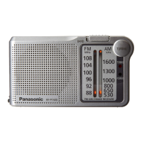
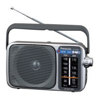
Details the frequency bands covered by the radio and reception parameters.

IF, Sensitivity, and Power Requirements

Specifies IF frequencies, sensitivity levels, and power source options.

Physical Dimensions and Weight

Provides physical size and mass specifications.

Location of Controls

Front Panel Controls Identification

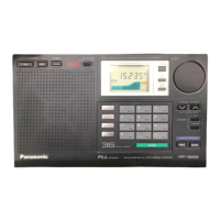
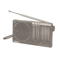
Identifies and describes all buttons and knobs on the front of the radio.

External Features and Connections

Details jacks, antenna, stand, and strap for connectivity.

Disassembly Instructions

Antenna, Cabinet, and PCB Removal

Steps to remove the telescopic antenna, cabinet parts, and main PCB.

Accessory and Component Removal

Procedures for removing other accessories and components.

Service Notes

Hold Switch and Battery Life Information

Covers hold switch operation and estimated battery performance.

Disassembly Procedures

Main PCB and Speaker Removal

Steps for removing the main PCB and speaker assembly.

Button, LCD, and Terminal Disassembly

Procedures for removing buttons, LCD, and battery terminals.

Strap, Tape, Stand, and Battery Assembly

Steps for removing strap, tape, stand, and battery components.

Schematic Diagram

Main Circuit Schematic

Diagram of the main circuit board components and connections.

Circuit Board and Wiring Diagrams

Main PCB Wiring Diagram

Illustrates wiring and component connections on the main PCB.

Alignment and Test Point Locations

Identifies alignment points and test points for measurements.

Terminal Guide and Measurements

Component Terminal Guide

Provides pinouts and functions for key ICs, transistors, and diodes.

Alignment Procedures and Equipment

Details required equipment and steps for radio alignment.

Alignment and Check Procedures

FM Alignment and Stop Checks

Procedures for FM auto stop, RF alignment, and frequency stop.

AM and SSB Alignment and Checks

Procedures for AM auto stop, SSB checks, and AM alignment.

Block Diagram

Radio Signal Flow Diagram

Illustrates the overall signal path and functional blocks.

Replacement Parts List

Cabinet Parts Location

Related product manuals