EasyManuals Logo

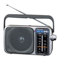
Panasonic RF-B45 Service Manual

Panasonic RF-B45
15 pages
To Next Page IconTo Next Page
To Previous Page IconTo Previous Page
Page #10 background imageLoading...
Page #10 background image
RF-B45
RF-B45
lm
TERMINAL
GUIDE
OF
IC’S,
TRANSISTORS
AND
DIODES
lm
MEASUREMENTS
AND
ADJUSTMENTS
AN7205
READ
CAREFULLY
BEFORE
ATTEMPTING
ALIGNMENT
Set
power
source
voitage
to
6
V
DC.
¢Set
tone
select
switch
to
HIGH.
Set
sensitivity
select
switch
to
DX.
Set
volume
control
to
center.
Set
AM
mode
select
switch
to
NOR/FIX.
SB80734ANDYT1
$81230AGRBT1
UPD1724GB561
BA10393FT
©
2e
EQUIPMENT
REQUIRED
Frequency
counter
®DC
digital
voltmenter
iF
monitor
scope
2SB709RTW
2SK160K4TW
Ampere
meter
*Oscilloscope
28C2404CTW
2SK160K5TW
.
Signal
generator
(FM/AM)
eFM/AM
IF
sweep
generator
c
D601RTW
2SK436A21TW
O
AVIDTOT4YRW
RS
BATTERY
CURRENT
CHECK
B
:
6
FREQUENCY
:
KD
DISPLAY
SETTING
REMARKS
D
1.
Power
switch
to
OFF.
2.
Check
for
less
than
50
pA.
(for
back-up
current
check)
1.
Power
switch
to
ON.
87.50
MHz
2.
Volume
control
to
minimum.
3.
Check
for
tess
than
70
mA.
2SK238K16TW
MA165TA
OASOA-M
MA7OOTA
RVD1SS135TA
SS
|
"Fe
MA724TW
MA4120MTA
MA151KTW
Co
&
cs
ae
Tae
ae
Cathode
A
Cathode
B
A
Anode
Anode
I
Zathode
Anode
1.
Power
switch
to
ON.
1620
kHz
2.
Volume
control
to
minimum.
3.
Check
for
less
than
80
mA.
MA701TW
RVDSVC203ATW
1MN11T110
LN376GC
PX-23
Cotnade
eB
arose
|
Anod
nove
AY:
anoe
|
ANCL?
carnode
Anode
cathode
a—@~
ceo
MA729TW
Anode
Cathode
a
Cathode
SS
mab
Anode
ra
Cothode
A
eFM
AND
AM
(SW)
VCO
ALIGNMENT
FREQUENCY
DC
DIGITAL
:
Cathode
Cathode
Anode
Ano
Fin
be
Function
Pip
|
Mark
ve
Functior
No.
Division
No.
Division
1
Device
select
signal
input
>
Output
terminals
for
LCD
t
5
Hl
0
jerals
si
seamen
29
terminal.
Set
the
terminal
high
to
is
10
,
select
adevice
and
low
to
deselect
:
Connect
to
1
=
———-
coe
Point
of
noninterference.
me)
Pt.
e
Adjust
VR3
for
55386+0.1
kHz
reading
on
frequency
counter.
12
30
Terminal
used
for
connecting
a
'
——-
(-)
}
ro)
Output
terminals
for
LCD
common
quartz
osillator.
;
i...
)
signals.
14
COMi
as
xi
'
Connects
a
75
kHz
quartz
Connect
to
15
Vv
oscillator.
.
F
through
10
pf.
Assure
that
the
frequency
control's
reading
is
variable
by
=
Reference
voltage
setting
Point
of
noninterlerence:
“(4)
rotating
the
frequency
contro!
(VR2).
16617]
CAP1+2
capacitor
connected
terminals
tor
32
vss4
Terminal
used
for
connecting
a
.
LCD.
capacitor
for
regulator
circuit.
+
18
|
vsse
.
a
ee
@SSB
RESTORATION
FREQUENCY
(B.F.0.)
CHECK
19
VDP
fe)
Variable
duty
port.
2
4
bit
I/O
port.
be
ee
20
CGP
te]
Clock
generator
port.
21
+—
NC
4
bit
Output
port.
Point
of
:
1.
Set
AM
mode
select
switch
to
SSB
position.
22
vob
'
A
voltage
of
1.8~3.6
V
supply
to
ne
2.
Assure
that
the
frequency
counter's
reading
is
459+
1
kHz.
this
terminal.
Output
terminals
for
key
signals.
fe
FM
IF
CHECK
23
VHF
—S
IF
SWEEP
jeanne
input
terminal
for
the
FM
local
;
GENERATOR
FREQUENCY
iF
MONITOR
24
HF
1
sllator
(VCO)
si
Input
terminals
for
key
retum,
BAND
DISPLAY
SCOPE
or
REMARKS
Seetiator
VCO)
sional.
signals
SETTING
|
OSCILLOSCOPE
.
CONNECTIONS
FREQUENCY
25
AMIN
a
26
vss1_
|
|
Ground
terminal.
st
coe
10.7
MHz
hho
(a)
Assure
that
the
waveform
shown
in
Fig.
3
ra
EQ.
i
o—
)
;
0
Output
terminals
for
LCD
segment
400
Hz
oniabout
re
(-)
appears
in
the
IF
monitor
scope
or
:
|
tcp1
signals.
30%
Mod.
(
)
i...
oscilloscope.
28
coz
|
0
PLL
error
output
termina’.
90
MHz
—15—

Questions and Answers:

Question and Answer IconNeed help?

Do you have a question about the Panasonic RF-B45 and is the answer not in the manual?

Panasonic RF-B45 Specifications

General IconGeneral
BrandPanasonic
ModelRF-B45
CategoryReceiver
LanguageEnglish

Related product manuals