EasyManuals Logo

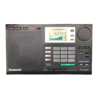
Panasonic RF-B45 Service Manual

Panasonic RF-B45
15 pages
To Next Page IconTo Next Page
To Previous Page IconTo Previous Page
Page #11 background imageLoading...
Page #11 background image
eFM
AUTO
STOP
ALIGNMENT
SIGNAL
GENERATOR
CONNECTIONS
|
FREQUENCY
Wad...(+)
FM
m)
RF-B45
RF-B45
@AM
AUTO
STOP
CHECK
FREQUENCY
DISPLAY
SETTING
DIGITAL
VOLTMETER
ADJUSTMENT
REMARKS
Adjust
T10
for
O+10
mV
(
_
Tio
reading
on
digital
i.
voltmeter.
106
MHz
CONNECTIONS
FREQUENCY
90
MHz
ial..(+)
(
400
Hz,
)
i...(-)
30%
Mod.
12.
dB
or
less
106
MHz
fiI...(+)
(
400
Hz,
)
3
30%
Mod.
12
dB
or
less
FM
STOP
FREQUENCY
ALIGNMENT
SIGNAL
GENERATOR
CONNECTIONS
FREQUENCY
105.95
MHz
400
Hz,
ce
hoa)
60
dB
107
MHz
e@FM
RF
ALIGNMENT
SIGNAL
GENERATOR
FREQUENCY
DIGITAL
BAND
DISPLAY
VOLTMETER
or
ADJUSTMENT
REMARKS
400
Hz,
30%
Mod.
26
dB
@AM
2nd
IF
ALIGNMENT
IF
SWEEP
GENERATOR
CONNECTIONS
FREQUENCY
Connect
to
{7235}
through
1
pF.
Gae...(+)
G.(-)
@AM
1st
IF
ALIGNMENT
SIGNAL
GENERATOR
BAND
CONNECTIONS
FREQUENCY
Connect
to
459
kHz
(
400
Hz,
)
30%
Mod.
55.845
MHz
Gat)
|
(som
)
.(-)
30%
Mod.
tense
SETTING
OSCILLOSCOPE
Earphone
Jack
(8Q)
Fabricate
the
plug
as
shown
in
Fig.
2
and
then
connect
the
lead
wires
of
the
plug
to
the
measunng
instrument,
e@Adjust
for
maximum
L15
output.
Earphone
Jack
(8)
set
in
a
Lab
@
Adjust
for
maximum
connact
the
lead
wires
of
output.
the
plug
to
the
measuring
instrument.
FREQUENCY
DISPLAY
OSCILLOSCOPE
SETTING
REMARKS
ADJUSTMENT
Adjust
VR4
for
maximum
output.
OUTPUT
REMARKS
Earphone
Jack
(8Q)
:
:
Febricate
the
plug
as
shown
||
'-
Press
the
Auto
Tuning
Switch
(S203)
to
start
the
auto
tuning.
in
Fig.
2
and
then
connect
tha}
2.
Assure
that
the
auto
tuning
is
stopped
at
107
MHz
and
a
signal
lead
wires
of
the
plug
to
the
is
received.
:
FREQUENCY
IF
MONITOR
DISPLAY
SCOPE
or
SETTING
OSCILLOSCOPE
ADJUSTMENT
REMARKS
Point
of
non-
interference.
(+)
®Adjust
for
maximum
..(-):
T6
and T11
output.
603
kHz
FREQUENCY
DISPLAY
OSCILLOSCOPE
ADJUSTMENT
SETTING
Earphone
Jack
(80)
Falricate
the
plug
as
;
;
10500
kHz
shown
in
Fig.
2
and
then
Adjust
for
maximum
connect
the
lead
wires
of
output.
the
plug
to
the
measuring
wnstrument.
Connect
to
through
15
pF.
400
Hz,
pore
nee
as
sown
in
Fig.
en
connect
the
ial...(+)
30%
Mod.)
||
OFS.
2
ans
nen
conn
...(-)
26
0B
measunng
instrument.
410600
kHz
Earphone
Jack
(8Q)
REMARKS
7
1.
Press
the
Auto
Tuning
Switch
(S203)
to
start
the
auto
tuning.
2.
Assure
that
the
auto
tuning
is
stopped
at
10600
kHz
and
a
i
signal
is
received.
|
———_——
Connect
to
Gia
through
15
pF.
400
Hz,
itbocok
Aa
rece
Rotate
the
fine
tuning
control
to
assure
that
the
best
sound
is
1
in
Fig,
jen
connect
a...(+)
30%
Mod.
head
tatocol
ookin
bs
output.
...(-)
26
6B
measuring
instrument.
@
ALIGNMENT
POINT
Refer
to
Circuit
Board
and
Wiring
Connection
Diagram
for
test
point
locations.
OUTPUT
10600
kHz
Earphone
Jack
(8Q)
REMARKS
AM
2m
iF
FM
AUTO
FM
VCO
AM(SWIVCO
FM
STOP
459k
Hz
STOP
9.00+0.IV
9.00
+0.1V
FREQUENCY
AM
2nd
OSC
AM
2nd
iF
AM
Ist
IF
SS.386MHz+IO0OHz
459
kHz
55.845MHz
To
Earphone
Jack
R=8Q
To
Measuring
Instrument
Fig.
2
OC
IN
6V
LOCAL
‘|
SENS
OX
1)
EXT
ANT
FM
RF
FM
RF
106.00MHz
90.00MHz
Fig.
1
Fig.
3
—18—

Questions and Answers:

Question and Answer IconNeed help?

Do you have a question about the Panasonic RF-B45 and is the answer not in the manual?

Panasonic RF-B45 Specifications

General IconGeneral
BrandPanasonic
ModelRF-B45
CategoryReceiver
LanguageEnglish

Related product manuals