EasyManua.ls Logo

Panasonic RJ-3600 User Manual

Panasonic RJ-3600
16 pages
To Next Page IconTo Next Page
Page #1 background imageLoading...
Page #1 background image
oRDER NO.
RD
7704-1418
Servlce Manual
RJ-3600
REGEIVEI}JIl[.
E
$
grr
Radio
4O-CHANNEL
CITIZENS
BAND
TRANSCEIVER
^*"".4.e
,%
e
dh
TSPECIFICATIONS
Power
Source
Receiver
Section
Frequency
Range.
Sensitivity:
Selectivity:
Adjacent
Channel Rejection:
Audio
Distortion
at
1
kHz:
Cross Modulation
Rejection:
120
V
(60
Hz), AC
13.8 V,
DC
26.965
MHz to 27.405 MHz
Less
than
-6
dB
(0.5
mV)
for 10
dB
S/N
at
1 kHz,3O/"
modulation
Bandwidth
5
kHz min. for
6 dB
55 dB
Less than
10"/o at2W
Better than 45 dB
Transmitter
Section
Frequency
Range:
Power
Output
at 1S.g
V,
DC:
Modulation:
Emission (Class
D
Operation):
Spurious
Emission:
Frequency
Tolerance:
Speaker:
Dimensions:
Weight:
lmpedance:
26.965
MHz to 27.4A5
MHz
4
W max.
Less than 1 00ol"
6A3
-60
dB
+0.005%
4"
(10
cm) PM
Dynamic
Speaker
13+"(Wide)x
5*"(Hish)
x
8#"
(Deep)
(337x
133x220
mm)
10
lb.
6
oz.
(4.7
kg)
with
Microphone
MicrophoneJack
........7000
Speaker . ........8O
EXTSpeakerJack
.........8O
AntennaJack
.....50O
Panasonic
Company
Division
of
Matsushita
Electric
Corporation ol
America
One
Panasonrc
Way
Secalcus.
N
J 07094
specifications
are
subject
to
change without
notice
for further
improvement.
Matsushita
Electric
of Hawaii,
lnc.
Matsushita
Etectric
of
Canada
Ltd
32OWarakam,loRoad
Honoluru
Hawail96817
40Ronso^Or,veRerdareOnr
MgW
tRs
Panasonic.
Question and Answer IconNeed help?

Do you have a question about the Panasonic RJ-3600 and is the answer not in the manual?

Panasonic RJ-3600 Specifications

General IconGeneral
Frequency range29.7-47 MHz
Channels16
Modulation typeFM
Power output5 W
Output Power5 W

Summary

Specifications

Power Source

Details the AC and DC power requirements for the transceiver.

Receiver Section

Lists sensitivity, selectivity, and distortion parameters for the receiver.

Transmitter Section

Outlines power output, modulation, and frequency tolerance for the transmitter.

Controls and Functions Overview

Controls and Their Functions

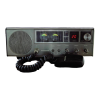
Explains the purpose and operation of each button, knob, and indicator on the transceiver.

Disassembly Procedures

Cabinet and Front Panel Removal

Step-by-step instructions for safely removing the cabinet cover and front panel assembly.

On Air Indicator Removal

Details the process for removing the On Air Indicator component.

Electrical Diagrams

Block Diagram

Provides a high-level functional overview of the transceiver's internal circuitry.

Circuit Schematics

Detailed Circuit Diagram

Shows the intricate wiring and component layout of the transceiver's circuitry.

Circuit Board Wiring Views

Circuit Board Wiring View

Illustrates the physical placement of components and connections on circuit boards.

Component Voltage Measurements

Transistor Voltage Measurements

Lists expected voltage readings at various transistor terminals for diagnostics.

Alignment Instructions

Alignment Points and Test Connections

Identifies specific points for alignment and shows test equipment connection diagrams.

Test Equipment and Procedures

Test Equipment and Oscillator Checks

Lists necessary test equipment and procedures for oscillator frequency checks.

VCO and 35.74 MHz Adjustments

Procedures for adjusting the VCO and 35.74 MHz component for optimal performance.

Transmitter Adjustments

Transmitter Oscillator and RF Tuning

Procedures for tuning the transmitter oscillator and RF output.

Transmission Frequency Check

Table listing expected transmitting frequencies for each channel.

Receiver Adjustments

IF, S-Meter, Squelch, and Modulation Tuning

Guides for adjusting IF stages, S-meter, squelch, and modulation levels.

Spurious Emission Check

Emission Checks in Receiving and Transmitting Modes

Procedures to check spurious emissions while the unit is in receiving and transmitting modes.

Component Locations

Cabinet and Chassis Parts Location

Diagrams showing the physical placement of external and internal chassis components.

Replacement Parts List

Integrated Circuits, Transistors, and Diodes

Lists part numbers for ICs, transistors, and diodes with their descriptions.

Component Details

Resistors, Switches, and Speaker

Lists part numbers and specifications for resistors, switches, and the speaker.

Related product manuals