EasyManua.ls Logo

Panasonic RX-CT900 - Page 15

Panasonic RX-CT900
26 pages
Print Icon
To Next Page IconTo Next Page
To Previous Page IconTo Previous Page
Loading...
aed
KP
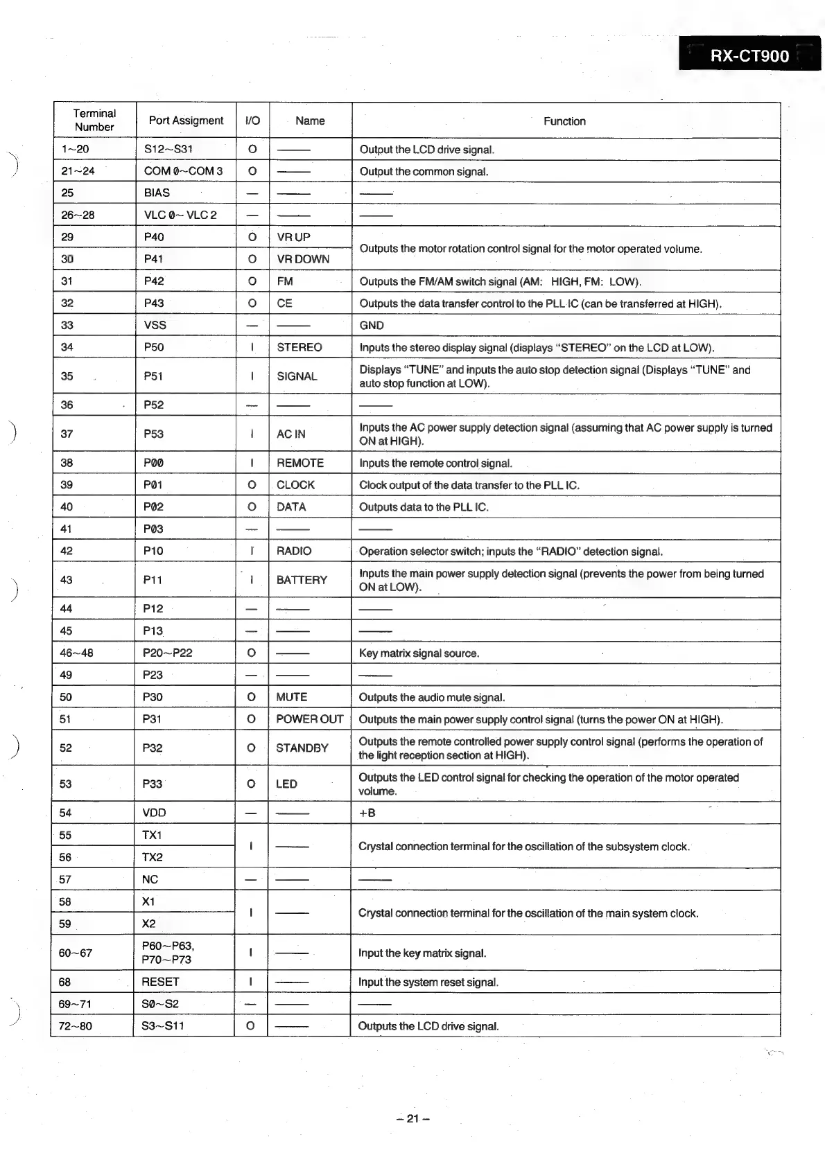
Terminal
Number
Port
Assigment
vO
1~20
$12~$31
21~24
COM
0~COM3
BIAS
VLC
@~
VLC
2
P40
P44
P42
Nh
a
VR.UP
VR
DOWN
FM
wo
oS
3
pe)
mp]
a
P43
3
VSS
34
P50
wo
Q
m
35
Ct
P51
|
SIGNAL
36
P52
P53
¥i
N
38
POO
39
PO1
[somes
[emt
fo
|——
Cs
[ro
fo
lw
ro.
|
rowen
our
51
P31
RESET
69~71
S0~S2
$3~S11
_
RX-CT900
|
ee
Output
the
LCD
drive
signal.
Output
the
common
signal.
Outputs
the
motor
rotation
control
signal
for
the
motor
operated
volume.
Outputs
the
FM/AM
switch
signal
(AM:
HIGH,
FM:
LOW).
Outputs
the
data
transfer
control
to
the
PLLC
(can
be
transferred
at
HIGH).
GND
Inputs
the
stereo
display
signal
(displays
“STEREO”
on
the
LCD
at
LOW).
Displays
“TUNE”
and
inputs
the
auto
stop
detection
signal
(Displays
“TUNE”
and
auto
stop
function
at
LOW).
inputs
the
AC
power
supply
detection
signal
(assuming
that
AC
power
supply
is
turned
ON
at
HIGH).
Operation
selector
switch;
inputs
the
“RADIO”
detection
signal.
Inputs
the
main
power
supply
detection
signal
(prevents
the
power
from
being
turned
ON
at
LOW).
Key
matrix
signal
source.
:
=
Outputs
the
audio
mute
signal.
Outputs
the
main
power
supply
control
signal
(turns
the
power
ON
at
HIGH).
Outputs
the
remote
controlled
power
supply
control
signal
(performs
the
operation
of
the
light
reception
section
at
HIGH).
Outputs
the
LED
contro!
signal
for
checking
the
operation
of
the
motor
operated
volume.
+B
Crystal
connection
terminal
for
the
oscillation
of
the
subsystem
clock.
Crystal
connection
terminal
for
the
oscillation
of
the
main
system
clock.
P60~P63,
ae
60~67
P70~P73
fof
—.
|
Input
the
key
matrix
signal.
Input
the
system
reset
signal.
;
Outputs
the
LCD
drive
signal.
=