Do you have a question about the Panasonic RX-CT820 and is the answer not in the manual?
Technical details for radio reception including frequency range and sensitivity.
Technical details for tape playback including track system and frequency range.
Power requirements, output power, speaker details, dimensions, and weight.
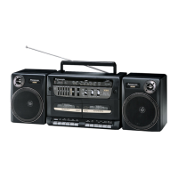
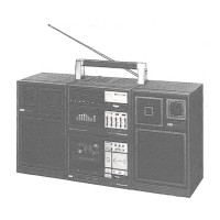
Identification and description of primary operational controls and tuner controls.
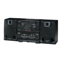
Identification and description of controls and connectors on the rear panel.
Step-by-step guide to remove the front panel, cassette lid, and tuning knob.
Procedures for removing the tape mechanism, record lever, and power P.C.B.
Steps for removing main/battery P.C.B.s, woofer, and tweeter speakers.
Steps for reassembling the front cabinet and handle after servicing.
Procedure for resolving tape tangles within the mechanism.
Detailed circuit diagram for the main operational components.
Diagrams for Graphic Equalizer, Power Supply, and Mechanism Control circuits.
Pinout and identification for integrated circuits, transistors, and diodes.
Diagram showing component placement on the main printed circuit board.
Component layout diagrams for auxiliary and power supply circuit boards.
Diagrams showing wiring connections between main P.C.B., auxiliary boards, and power supply.
Guidelines and precautions before performing alignment procedures.
Steps for aligning AM-IF, MW-RF, and SW1-RF circuits.
Procedures for aligning SW2-RF, FM-IF, and FM-RF circuits.
Instructions and procedure for aligning tape speed on cassette decks.
Visual reference showing locations of alignment adjustments on the circuit board.
Exploded views and part numbers for Deck 1 and Deck 2 mechanism components.
Exploded views and part numbers for main unit and speaker cabinet components.
Comprehensive lists of mechanism parts, replacement parts, and electronic components.
List of packing materials and accessories included with the product.
| CD Player | Yes |
|---|---|
| Radio Tuner | Yes |
| Bluetooth | No |
| USB Port | No |
| Cassette Deck | Yes |
| Tuner Bands | AM/FM |
| Weight | 7.2 kg |
| Speakers | 2 Speakers |