Slide # 23
Models:
SA-PT660
SA-PT760
SA-PT960
SA-PT1060
SH-FX67, 85
Outline
Wireless
Mech
Pwr Supply
Protection
Audio
Mech Troubleshooting. Is it the Mech or the Circuitry?
When the mechanism does not work correctly, is the problem mechanical? Is it
a sensor under the mech? Is it on the main board by the microprocessor?
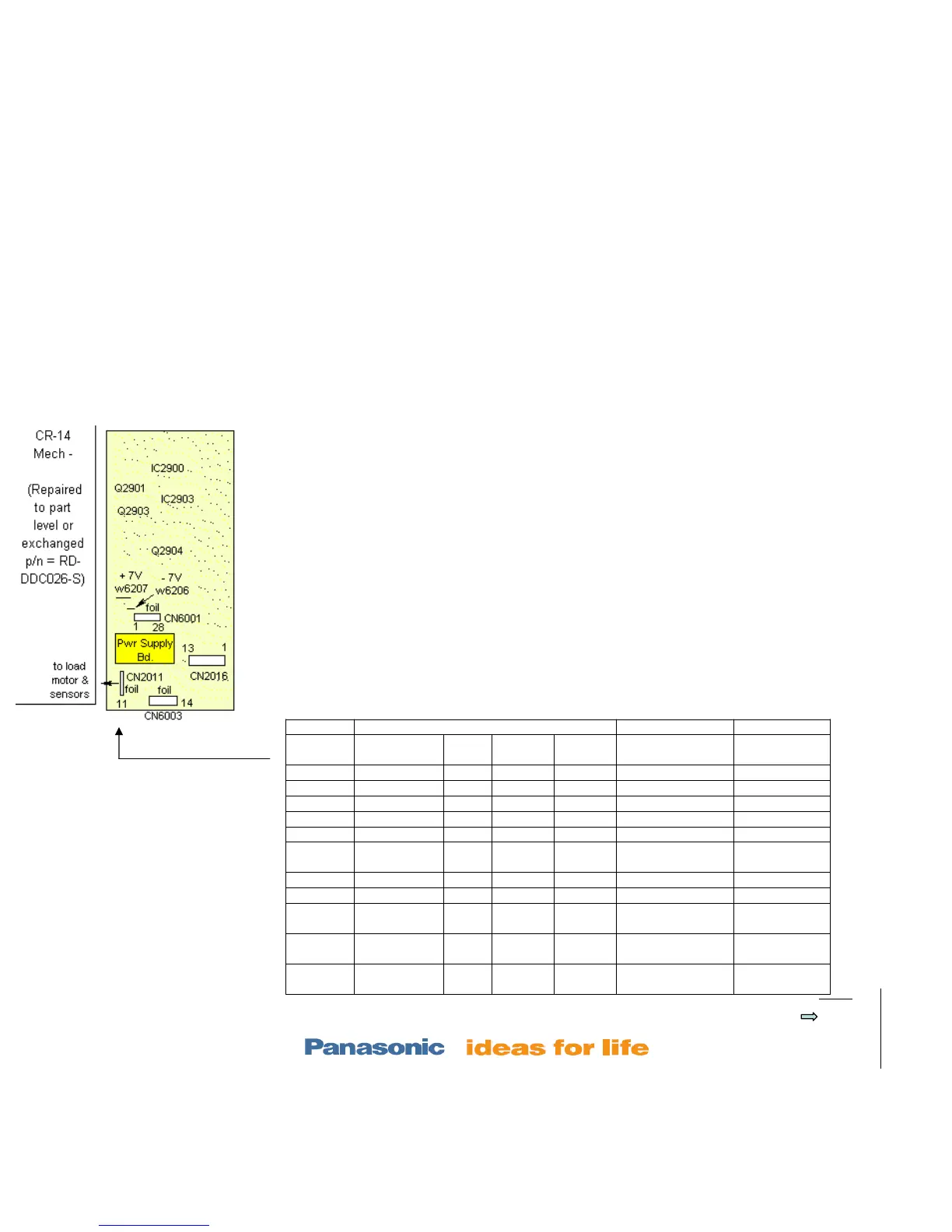
Isolation Procedure:
1. Note which tray is in the laser assembly. Unplug the ribbon cable at CN2011.
2. Compare the dc voltages at the 11 pin connector (without the cable inserted) to the
“No cable” column voltages shown below. If any are different, the main board is at fault.
Check the pull up resistors and check the main board for cracks.
3. Note the position of the trays in the mechanism. Reconnect CN2011.
4. Compare the dc voltages at the same CN2011 connector to the corresponding
column in the chart below (cable inserted). Pictures are on the previous page.
If any of the voltages do not agree with the chart below, the corresponding sensor (Q1-5, Sw3,4) is
bad. If the voltages all agree, the mechanical assembly is defective or out of alignment. Replace
the assembly, or do the prev. transfer alignment.
CN2011 Connector Voltage
CN2011/
pin
No CN2011
cable
Tray
1 in
Trays
2-5 in
All trays
out
CN2011/pin
corresponds to:
Changes
during
1 8.2V 7.5V 7.5Vdc 7.5Vdc Motor driver Vcc
2 gnd No change
3 5Vdc 5Vdc 5Vdc 5Vdc Q4 Mode sensor Elevator dwn
4 gnd
5 5Vdc 0Vdc 5Vdc 0Vdc SW3 Top sw
6 5Vdc 0Vdc 0Vdc 0Vdc Q1 UD (lever
sensor)
Trays
stocked
7 0Vdc 0Vdc 0Vdc 0Vdc Motor fwd
8 0Vdc 0Vdc 0Vdc 0Vdc Motor rev
9 5Vdc 0Vdc 0Vdc 0Vdc Q2 close (gear
sens)
10 5Vdc 0Vdc 0Vdc 5Vdc Q3 home (gear
sens)
Tray moves
back / forth
11 5Vdc 0Vdc 0Vdc 0Vdc Q5 open (lever
sens)
H at tray out