EasyManua.ls Logo

Panasonic SB-MAX750 User Manual

Panasonic SB-MAX750
134 pages
To Next Page IconTo Next Page
Page #1 background imageLoading...
Page #1 background image
© Panasonic Corporation 2013. All rights reserved.
Unauthorized copying and distribution is a violation
of law.
MEX1310012CE
CD Stereo System
Model No. SA-MAX750LMK
Product Color: (K)...Black Type
TABLE OF CONTENTS
1 Safety Precautions
1.1. General Guidelines
1.2. Before Repair and Adjustment
1.3. Protection Circuitry
1.4. Caution For Fuse Replacement
1.5. Safety Parts Information
2 Warning
2.1. Prevention of Electrostatic Discharge (ESD)
to Electrostatically Sensitive (ES) Devices
2.2. Precaution of Laser Diode
2.3. Service caution based on Legal restrictions
2.4. Handling Precautions for Traverse Ass’y
2.5. Grounding for electrostatic breakdown
prevention
3 Service Navigation
3.1. Service Information
3.2. Firmware Update Procedure
4 Specifications
5 General/Introduction
5.1. Media Information
6 Location of Controls and Components
6.1. Remote Control Key Button Operation
6.2. Main Unit Key Button Operation
7 Service Mode
7.1. Cold-Start
7.2. Doctor Mode Table
7.3. Reliability Test Mo
de (CD Mechanism Unit)
7.4. Self-Diagnostic Mode
7.5. Self-Diagnostic Error Code Table
7.6. Sales Demonstration Lock Function
8 Troubleshooting Guide
9 Disassembly and Assembly Instructions
Please refer to the original service manual for:
CD Mechanism Unit, Mechanism (BRS11C) Order No. PSG1201019AE
Speaker system SB-MAX750PHK, Order No. MEX1310013AE
Nota: El idioma original de este Manual de Servicio es en idioma inglés, sin embargo algunas notas
aquí mencionadas serán escritas en español para mejor descripción para Centros de Servicio de México.

Table of Contents

Question and Answer IconNeed help?

Do you have a question about the Panasonic SB-MAX750 and is the answer not in the manual?

Panasonic SB-MAX750 Specifications

General IconGeneral
BrandPanasonic
ModelSB-MAX750
CategoryStereo System
LanguageEnglish

Summary

Safety Precautions

General Guidelines

General safety guidelines for equipment servicing.

Before Repair and Adjustment

Precautions before starting repair or adjustment procedures.

Caution For Fuse Replacement

Important cautions regarding fuse replacement procedures.

Safety Parts Information

Lists safety-critical components requiring specific replacement parts.

Warning

Prevention of Electrostatic Discharge (ESD) to Electrostatically Sensitive (ES) Devices

Techniques to prevent damage to sensitive electronic components from static discharge.

Precaution of Laser Diode

Safety precautions when handling the laser diode in the optical pickup unit.

Handling Precautions for Traverse Ass’y

Specific handling precautions for the optical pickup unit traverse assembly.

Grounding for electrostatic breakdown prevention

Methods for grounding to prevent electrostatic discharge damage.

Specifications

Location of Controls and Components

Remote Control Key Button Operation

Explains the function of each button on the remote control.

Service Mode

Cold-Start

Procedure to perform a cold start or initialize the unit to shipping mode.

Doctor Mode Table

Table detailing various diagnostic modes accessible via the doctor mode.

Self-Diagnostic Mode

Information on entering self-diagnostic mode and displaying error codes.

Self-Diagnostic Error Code Table

Table listing error codes and their corresponding diagnosis and descriptions.

Troubleshooting Guide

Disassembly and Assembly Instructions

Main Components and P.C.B. Locations

Diagrams showing the location of major components and printed circuit boards.

Disassembly of Top Cabinet

Step-by-step instructions for disassembling the top cabinet.

Disassembly of Front Panel Unit

Instructions for disassembling the front panel unit.

Disassembly of FL Display P.C.B.

Steps to remove the FL display printed circuit board.

Disassembly of Bluetooth P.C.B.

Procedure for disassembling the Bluetooth printed circuit board.

Disassembly of CD Mechanism Unit

Procedure for disassembling the CD mechanism unit.

Disassembly of Main P.C.B.

Detailed steps for disassembling the main printed circuit board.

Disassembly of SMPS P.C.B.

Instructions for disassembling the switching mode power supply printed circuit board.

Schematic Diagram

Exploded View and Replacement Parts List

Exploded View and Mechanical Replacement Part List

Exploded views and lists of mechanical replacement parts.

Mechanical Replacement Part List

List of mechanical replacement parts with safety information.

Electrical Replacement Part List

List of electrical replacement parts with safety information.
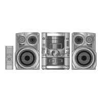
Related product manuals