Do you have a question about the Panasonic SC-UA3GS and is the answer not in the manual?
Lists critical safety components marked with symbols for proper replacement to prevent hazards.
Detailed schematic for the main Micon circuit, part one, showing component connections and signal paths.
Continuation of the main Micon circuit schematic, part two, detailing further component interconnections.
Schematic diagram for the main Tuner and AUX circuit, illustrating signal flow for these functions.
Layout diagram for the main printed circuit board (Side B) for SC-UA3GS/GSX models.
Layout diagram for the main printed circuit board (Side B) for SC-UA3PP models.
Details differences in part numbers and specifications between model variants.
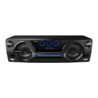
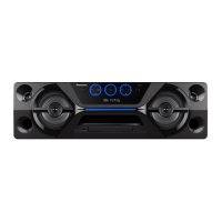
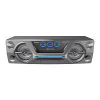
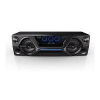
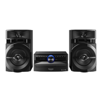
This document serves as a service manual for the Panasonic Compact Stereo System, Model Numbers SC-UA3GS, SC-UA3GSX, and SC-UA3PP, all in a black (K) finish. It is a simplified manual intended to be used in conjunction with the original service manual, Model No. [SC-UA3E-K, Order no. PSG1705009CE].
The manual begins with a crucial WARNING emphasizing that the service information is designed for experienced repair technicians only. It explicitly states that servicing products powered by electricity should only be performed by professional technicians to prevent serious injury or death. This highlights the complexity and potential hazards associated with repairing the device, underscoring the need for specialized knowledge.
An IMPORTANT SAFETY NOTICE follows, drawing attention to special components critical for safety, marked with a triangle (▲) in the diagrams and parts lists. These parts must be replaced with manufacturer-specified components to prevent shock, fire, or other hazards, and the original design should not be modified without permission. This emphasizes the importance of using genuine parts and adhering to design specifications for safety.
The TABLE OF CONTENTS outlines the manual's structure, covering notes, safety precautions (including safety part information), specifications, schematic diagrams (Main (Micon) Circuit and Main (Tuner AUX) Circuit), printed circuit board layouts (Main P.C.B. for both SC-UA3GS/GSX and SC-UA3PP-K), packaging details, and replacement parts lists (specifically highlighting differences). This comprehensive structure ensures that technicians have access to all necessary information for servicing.
1 Notes reiterates that the manual provides technical information for service personnel to understand and service the model, advising to order parts using the parts list rather than drawing reference numbers. It also states that any circuit changes or modifications will be followed by a supplement service manual. This section clarifies the intended use of the manual and how updates are managed. It also specifies that this simplified manual focuses on safety precautions, specifications, main schematics (MICON and TUNER AUX), main PCB, packing, and a differences list for replacement parts, referring to the SC-UA3E-K manual for other details.
2 Safety Precautions details the Safety Part Information, providing a list of critical components marked for safety. This list includes items such as NAMEPLATES (TBMK4905 for UA3GS-K, UA3GSX-K; TBMK4908 for UA3PP-K), TRAVERSE ASS'Y (TXQ0011), AC CORDS (various part numbers for different models and regions), O/I (Operation/Instruction) books (various part numbers for different languages), and SMPS MODULES (N0AE1GN00001 for UA3GS-K, UA3GSX-K; N0AE1GN00004 for UA3PP-K). The inclusion of specific part numbers and their corresponding models ensures precision in replacement and maintenance, reinforcing the safety guidelines.
3 Specifications provides a detailed overview of the system's technical capabilities:
Amplifier section:
Dimensions (W x H x D): 650 mm x 196 mm x 274 mm (25 5/6" x 7 6/8" x 10 7/8" for PP).
Mass: 6.1 kg.
Operating temperature range: 0 °C to +40 °C.
Operating humidity range: 35% to 80% RH (no condensation).
Power Consumption in standby mode (approximate): 0.5 W.
Power Consumption in standby mode (approximate) (When BLUETOOTH STANDBY set to "ON"): 0.6 W.
Tuner section:
Disc section:
Terminal section:
Bluetooth® section:
General:
4 Schematic Diagram includes detailed circuit diagrams for the Main (Micon) Circuit (1/2 and 2/2) and Main (Tuner AUX) Circuit. These diagrams are essential for technicians to understand the internal wiring and component connections, facilitating troubleshooting and repair. Signal lines for +B, AUX/TUNER, FM, CD, TUNER, and USB are clearly indicated, which helps in tracing signal paths.
5 Printed Circuit Board provides layouts for the Main P.C.B. (Side B) for both SC-UA3GS/GSX-K (TNPA6463AE) and SC-UA3PP-K (TNPA6463AF). These diagrams show the physical arrangement of components on the circuit board, including connectors for FM ANT, AUX IN, OPTICAL DIGITAL AUDIO IN, and TO SPEAKERS. This visual guide is crucial for identifying components and their locations during repair.
6 Packaging illustrates the system's packaging, including the arrangement of the SC-UA3 unit, polyfoam inserts (top front, top rear, bottom left, bottom right), and accessories bag. The accessories bag contains the remote control, various AC cords (specific to GS/GSX and PP models), O/I book, and FM indoor antenna. This section is useful for understanding how the product is shipped and for ensuring all components are present.
7 Replacement Parts List details the Parts List Difference points between the SC-UA3E-K, SC-UA3GS/GSX-K, and SC-UA3PP-K models. This list is critical for ordering the correct parts for each specific model. It includes differences in PCBs (Main, Panel, Mic, USB, LED), ICs, resistors, cabinets (Rear, Front Panel, Bottom Frame), nameplates, packing cases, AC cords, O/I books, antenna plug adaptors, and optical cables. The explicit listing of different part numbers for various models and regions (e.g., AC cords for GS/GSX only vs. PP only, O/I books for different languages) is invaluable for accurate parts procurement and maintenance. For instance, PCB7 (SMPS MODULE) has different part numbers for SC-UA3E-K/SC-UA3GS/GSX-K (N0AE1GN00001) and SC-UA3PP-K (N0AE1GN00004), indicating internal power supply variations. Similarly, the AC CORD (A2) has distinct part numbers for GS/GSX (K2CP2YY00061, K2CQ2YY00107, K2CT2YY00089) and PP (K2CB2YY00065), reflecting regional power plug differences. The inclusion of "A" marks for safety-critical parts in this list further reinforces the safety guidelines mentioned earlier.
In summary, this service manual provides comprehensive technical and safety information essential for professional technicians to maintain and repair the Panasonic Compact Stereo System models SC-UA3GS, SC-UA3GSX, and SC-UA3PP. It emphasizes safety, precise part replacement, and detailed technical specifications, ensuring the longevity and safe operation of the device.
| Brand | Panasonic |
|---|---|
| Model | SC-UA3GS |
| Category | Stereo System |
| Language | English |