EasyManua.ls Logo

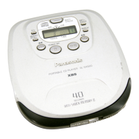
Panasonic SL-SX510 - Page 10

Panasonic SL-SX510
15 pages
To Next Page IconTo Next Page
To Previous Page IconTo Previous Page
Loading...
5 Printed Circuit Board and Wiring Connection Diagram
A
B
C
DE
F
1
2
3
4
5
6
7
8
1
5
10
15
16
17
20
25
35
45
55
30
60
64
50
40
32
33
48
49
IC301
13579
1113151719
21 23 25 27 29
2468
1012 1416
1
3
5
7
9
11
13
15
2
4
6
8
10
12
14
16
18
20 22 24 26 28 30
CN301
CN101
1
5
10
15
20
21
25
35
30
40
1
5
6
7
10
12
13
15
18
19
20
24
IC502
1
4
5
8
IC701
1
21
510
30
40
15
25
35
20
IC401
JK11
C606
C605
C
B
E
Q602
C608
C607
R605
R607
S201
JK601
C37
C16
R29
R13
L11
C101
JK551
L13
L12
C10
C21
R22
RJ2
R27
C13
C14
C19
C201
R202
R203
R508
1
2
4
6
8
7
5
3
CN401
VR11
C507
D901
C
C
B
E
B
Q902
C
B
E
Q901
R604
C610
RJ510
RJ506
RJ504
RJ508
RJ502
R511
R714
X501
C705
C706
C702
JK701
R433
C701
C437
C27
C28
C401
C402
C438
C411
C411
C408
C951
C405
C410
R439
R411
R410
R902
R907
R908
R956
R951
R932
R931
R903
C
B
E
Q903
C
B
E
Q951
E
C
B
Q904
C
BE
Q953
D911
D903
C404
L401
DC IN 4.5V
SHORT LAND
OPT
OUT
OUT
OFF
ON
MODE
HOLD
VOLUME
HEADPHONES
ICP11
CN51
IC11
S310
S309
C707
VR701-2
VR701-1
Q11
B
E
C
RANDOM
NORMAL
RESUME
GND
RF
VREF
VDD
(SIDE: A)
LCD301
TRAVERSE UNIT
OPERATION/LCD UNIT
BATTERY CASE
2 R6/LR6(UM-3)
BATTERIES . . . 3V
REP2737A-M.....[GC,GK]
REP2737B-M.....[GN]
For [GC,GK] areas.
For [GN] area.
X501
32 1
For [GN] area.
For [GN]
area.
For
[GC,GK]
areas.
For
[GC,GK] areas.
For
[GC,GK]
areas.
For [GN]
area.
For
[GC,GK]
areas.
For
[GC,GK]
areas.
Note: This printed circuit board diagram may be modified at
any time with the development of new technology.
SL-SX510
10

Other manuals for Panasonic SL-SX510

Related product manuals