Do you have a question about the Panasonic SX-KC600 and is the answer not in the manual?
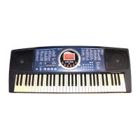
Details about the keyboard's keys and touch sensitivity.
Information on polyphony, sounds, and effects.
Details on rhythm count and variation.
Information on performance pad banks and memories.
Lists auto play chord modes.
Information on music trainer features.
Information on floppy disk drive specifications.
General safety instructions for safe operation.
Minimum spacing requirements for primary and secondary circuits.
Precautions for servicing and part replacement.
Describes how to perform insulation resistance tests.
Describes the initial step of disassembly.
Explains how to remove specific circuit boards.
Describes removing the disk drive and speakers.
Explains removal of keyboard interface circuit boards.
Describes how to remove the keyboard key sets.
Describes tests for the sound system.
Describes tests for panel switches and LEDs.
Describes tests for the LCD display.
Describes tests for the floppy disk controller.
Highlights critical safety components and parts.
Explains symbols used for resistors and capacitors.
Specifies measurement conditions for the main PCB.
Specifies measurement conditions for the FAJ PCB.
Refers to the layout of specific PCBs.
Refers to layouts of more specific PCBs.
Functionality for recording and playing back performances.
Feature for automatic accompaniment based on chords.
Function to develop rhythm sense.
Adds phrases to playing via pad buttons.
Sets appropriate sounds and rhythms automatically.
Aids in improving performance with Beat Master, Chord Finder, Minus One.
Stores current instrument settings for easy recall.
Describes the steps to access and use menu functions.
Details how to adjust various part settings.
Adjusts volume levels for each part.
Selects sound settings for each part.
Configures local control for MIDI transmission.
Sets internal or external MIDI clock.
Resets all instrument settings to factory defaults.
Covers issues related to sound output and button function.
Covers disk drive noise and memory clearing.
Covers external noise and cabinet warmth.
Connects an optional foot switch.
Outputs audio to headphones or amplifiers.
| Number of Keys | 61 |
|---|---|
| Rhythms | 100 |
| Display | LCD |
| Touch Sensitivity | Yes |
| Power Source | AC adapter or batteries |