Do you have a question about the Panasonic tc-32lx14 and is the answer not in the manual?
Techniques to reduce component damage from static electricity, including grounding and handling precautions.
Step-by-step instructions on accessing the service mode using the remote control and main unit buttons.
Explains how to access and use the SRV-TOOL function within service mode for diagnostics.
Instructions for accessing self-check indications to diagnose IIC bus line issues and perform factory resets.
A chart detailing Power LED blink patterns and their corresponding error causes for troubleshooting.
A flowchart guiding the technician through troubleshooting steps for "No Power" indication based on LED status.
Lists various test points on the A-board with their specified voltage values under reception conditions.
Procedure for adjusting picture levels using an RF signal and service mode settings for optimal display.
Steps for adjusting picture levels using a VIDEO signal, involving service mode and contrast settings.
Procedure for adjusting picture levels using a YUV signal, focusing on service mode and contrast adjustments.
Part 1 of the A-Board schematic, detailing ICs and connections related to video and memory interfaces.
Part 2 of the A-Board schematic, illustrating flash memory, SD card slot, and other IC connections.
Part 3 of the A-Board schematic, showing power supply circuits, analog ASIC, and voltage regulators.
Part 4 of the A-Board schematic, focusing on audio IC and speaker connections.
Part 5 of the A-Board schematic, detailing level shift IC and temperature sensor connections.
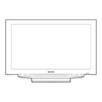
Visual exploded view of the TV assembly with numbered parts for identification.
| Screen Size | 32 inches |
|---|---|
| Display Type | LCD |
| Resolution | 1366 x 768 |
| Aspect Ratio | 16:9 |
| Speakers | 2 x 10W |
| Viewing Angle | 170° (Horizontal), 170° (Vertical) |
| Inputs | Composite, Component |