EasyManua.ls Logo

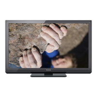
Panasonic TC-P55ST30 - User Manual

Panasonic TC-P55ST30
115 pages
To Next Page IconTo Next Page
Loading...
© Panasonic Corporation 2011.
Unauthorized copying and distribution is a violation
of law.
ORDER NO.MTNC110214CE
B34 Canada: B62
55 inch Class 1080p Plasma HDTV
Model No. TC-P55ST30
GPF14DU Chassis

Table of Contents

Questions and Answers:

Panasonic TC-P55ST30 Specifications

General IconGeneral
Screen Size55 inches
Display TypePlasma
3D TechnologyActive 3D
HDMI Ports4
Refresh Rate600Hz Sub-field Drive
Smart TV PlatformViera Connect
Audio Output20W (10W x 2)
Resolution1920 x 1080
NetworkingEthernet
InputsHDMI, Component, Composite, USB, Ethernet
Wi-FiOptional (via USB adapter)

Summary

Safety Precautions

General Guidelines & Leakage Current Checks

General guidelines for repairs and procedures for leakage current checks.

Warning & ESD Prevention

Electrostatic Discharge (ESD) Prevention

Techniques to reduce component damage from electrostatic discharge during handling.

Lead-Free Solder Information

Information on lead-free solder, its properties, and usage guidelines.

Service Navigation

PCB Layout & Applicable Signals

Diagrams showing PCB layout and details on compatible input signals.

Specifications

Technical Descriptions

KEY Specification for Content Protection

Details on the key specifications for digital content protection technologies.

Service Mode Operations

Entering, Exiting & Adjustment Mode

Procedures for accessing, exiting service mode, and listing adjustment parameters.

Service Mode Options & Tools

Service mode options like Mirror, Tool Mode, Hotel Mode, and Data Copy.

Troubleshooting Guide

IIC Bus Check & Power LED Diagnostics

Procedures for checking IIC bus lines and interpreting Power LED blinking patterns.

Common Fault Diagnosis

Troubleshooting steps for No Power, No Picture, and Local Screen Failure.

Service Fixture & Tools

SC Jig Usage for Board Diagnosis

Instructions for using the SC jig to diagnose SC or SU/SD board failures.

Disassembly and Assembly Instructions

Cover, Inlet, and Board Removals

Procedures for removing covers, AC inlet, P-Board, Tuner, and A-Board.

Side Unit, Speaker, and Scan Board Removals

Procedures for removing side unit, speakers, SU, SD, SC, and SS boards.

Bracket, Chassis, and Other Board Removals

Procedures for removing stand bracket, chassis parts, S-Board, and contact metals.

Plasma Panel and Driver Board Replacement

Procedures for removing C1/C2/C3 boards, K/V boards, and replacing the plasma panel.

Measurements and Adjustments

Vsus Selection

Procedure for selecting the correct Vsus voltage level after panel replacement.

RF Video Contrast & White Balance Adjustments

Procedures for RF video contrast and white balance adjustments.

Block Diagrams

Main and Detailed Block Diagrams

High-level and detailed block diagrams illustrating TV circuitry and components.

Wiring Connection Diagrams

Cable Assembly Caution & Wiring

Caution for cable assembly and diagrams illustrating internal wiring connections.

Schematic Diagram Notes

Replacement Parts List Notes

Exploded Views and Accessories

Exploded Views 1 & 2

Diagrams illustrating the physical assembly and disassembly of the TV components.

Included Accessories

Illustration of included accessories such as remote control and cables.

Related product manuals