Do you have a question about the Panasonic Toughbook CF-30CTQAZBM and is the answer not in the manual?
| Operating System | Windows XP Professional |
|---|---|
| Graphics | Intel GMA X3100 |
| Rugged | Yes |
| Processor | Intel Core 2 Duo Processor L7500 1.6GHz |
| Wireless | Intel PRO/Wireless 4965AGN |
| Ports | USB 2.0, Serial, VGA, Ethernet, Modem, Audio, PCMCIA |
| Weight | 8.2 lbs |
| Durability | MIL-STD-810F, IP54 certified |
| Optical Drive | DVD Super Multi |
| Wired Protocol | Gigabit Ethernet |
| Display | 13.3" XGA LCD (1024x768) |
Critical safety notice regarding service procedures and potential risks.
Guidance on proper earthing, fuse replacement, and wiring for UK power connections.
Details on compliance with DHHS Rules and European Standard EN60825 for laser products.
Instructions to avoid hazardous radiation exposure and warnings about servicing laser components.
Cautions for lithium battery replacement, potential explosion risks, and proper disposal methods.
Advice on avoiding heat, short circuits, proper charging, and recognizing battery degradation.
Details on CPU, memory, display, storage, and display resolutions.
Information on wireless LAN, Bluetooth, ports, and card slots.
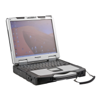
Identifies external parts like antennas, slots, LEDs, and buttons with their functions.
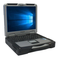
Locates and names ports such as USB, LAN, audio, power, and serial on the device.
Illustrates the block diagram showing CPU, memory, storage, and peripheral connections.
Outlines the general steps for diagnosing and repairing faults, including self-tests.
Flowchart for resolving issues like no power, dark display, and startup failures.
Explains beep patterns and their corresponding error messages for main board issues.
Lists BIOS error codes related to disk, keyboard, RAM, battery, and CMOS checksum.
Covers errors for cache, CPU, EISA, DMA, NMI, IRQs, OS detection, and parity checks.
Steps to start the diagnostic utility, configure setup, and begin tests.
Instructions for performing full system diagnostics and specific component tests.
Explains the display interface, status indicators (PASS, FAIL), and test outcome interpretation.
How to choose specific devices for testing and properly exit the diagnostic utility.
Details standard and enhanced tests for CPU, RAM, HDD, MODEM, Wireless LAN, Sound, USB, LAN, PC Card, SD, Keyboard, Touch Pad, DVD-ROM.
Covers tests for Touch Screen, Bluetooth, Wireless WAN, Floppy, Video, GPS, IEEE1394, Express Card, Smart Card, Serial Port, Parallel Port.
Illustrates the wiring paths for various internal components and external interfaces.
Essential pre-disassembly tasks including system shutdown and disconnecting power.
Step-by-step guide for safely removing the HDD and its associated parts.
Instructions for removing the keyboard, KB cover, and hinge covers.
Steps for removing keyboard/LCD cable covers, GPS PCB, and Bluetooth PCB.
Guide for removing the DIMM cover, bottom cover, and memory card.
Procedure for removing the Flexible Printed Circuit (FPC) for the HDD battery.
Steps to disconnect cables and remove the main Printed Circuit Board.
Instructions for removing SD PCB, Express Card, PCMCIA Card, and I/O PCB.
Steps for removing the palm top cover, touchpad, LED PCB, and related parts.
Guide for detaching the display unit from the main chassis.
Steps to remove the Inverter PCB, TS PCB, and LCD Unit.
Steps for installing the left and right antenna PCBs and securing covers.
Reassembly steps for the Inverter PCB, TS PCB, and LCD Unit.
Instructions for reassembling the LCD rear cabinet, hinges, and side covers.
Steps to reinstall the display unit and assemble the handle and power switch.
Reassembly of palm top cover, touchpad, LED PCB, and related parts.
Steps for assembling the power switch module and the palm top cover assembly.
Instructions for installing the I/O PCB and setting the SD, Express, and PCMCIA cards.
Detailed steps for installing and connecting the Main PCB, including modem and ICH plate.
Steps for installing the LAN module, modem, and MDC components.
Instructions for installing the PAD PCB and connecting its associated cables.
Steps for installing the FPC HDD Battery Pack and related components.
Steps for installing the USB PCB and Antenna PCBs, including cable connections.
Instructions for reinstalling the DIMM cover and bottom cover, including the memory card.
Steps for installing the GPS PCB, Bluetooth PCB, and associated cables.
Instructions for setting the keyboard, KB cable cover, and LCD cable cover.
Steps for reinstalling the KB cover, hinge covers, and keyboard assembly.
Final steps for installing the battery pack and HDD pack.
Exploded view of the main chassis and surrounding components, detailing screw types and locations.
Exploded diagram showing internal parts like drives, connectors, and smaller assemblies with screw details.
Exploded view illustrating the main board, modem, ICH plate, and related components with screw specifications.
Exploded diagram of the chassis, base plate, and associated mounting hardware.
Exploded view of the display unit, including screen, bezel, and mounting hardware.
Detailed exploded view of the display bezel and its mounting screws.
Exploded diagram of the computer frame, housing, and related mounting screws.
Comparison table of part numbers for different models, including descriptions and quantities.