EasyManua.ls Logo

Panasonic TX-25FG20R - User Manual

Panasonic TX-25FG20R
34 pages
Print Icon
To Next Page IconTo Next Page
Loading...
Power Source AC AUTO 110-240V, 50/60Hz
Power Consumption 199 W
Standby condition : 2 W
Aerial Terminal Impedance : 75, Coaxial type
Tuning System Frequency Synthesizer
Auto Search Tuning
Pos : 100 Positions
Receiving System 17 Systems
Receiving Channels Regular TV
VHF BAND 2-12 (PAL/SECAM B, K1)
0-12 (PAL B AUST.)
1-9 (PAL B N.Z.)
1-12 (PAL/SECAM D)
1-12 (NTSC M Japan)
2-13 (NTSC M U.S.A)
UHF BAND 21-69 (PAL G, H, I/SECAM G, K, K1)
28-69 (PAL B AUST.)
13-57 (PAL D, K)
13-62 (NTSC M Japan)
14-69 (NTSC M U.S.A.)
CATV S1-S20 (OSCAR)
1-125 (U.S.A. CATV)
C13-C49 (JAPAN)
S21-S41 (HYPER)
Z1-Z37 (CHINA)
5A, 9A (AUST)
Intermediate Frequency 38.0 MHz
© 2005 Matsushita Electric Industrial Co., Ltd. All
rights reserved. Unauthorized copying and
distribution is a violation of law.
TX-25FG20R
GP4 Chassis
Video 31.5 MHz (D, K) / 32.5 MHz (B, G)
32.0 MHz (I) / 32.5 MHz (M)
Sound 33.57 MHz (PAL) /
Colour 33.6 MHz (SECAM)
34.42 MHz (NTSC) /
33.75 MHz (SECAM)
Receiving Stereo Sound System AV STEREO
Video/Audio/Terminals
AV 1, 2, 3
Y/P
B
/P
R
(Phone Type) Y:1.0Vp-p 75 PB,
PR:0.7Vp-p 75 Video 1.0Vp-p
75 Audio Approx. 400mV 47K
Video 1.0Vp-p 75
Monitor Out Audio Approx. 400mV 47K
High Voltage 30.0 (+ -1.0kV) at zero
beam current
Picture Tube A59QDF891X Type 25 (59 cm)
Measured diagonally,
104° deflection
Audio Output 16 W speaker
Dimensions (W x D x H) 717 mm x 502 mm x 530.5 mm
Weight (Mass) 31 kg (Net)
Note:
Specifications are subject to change without notice. Mass and
dimensions shown are approximate.
Colour Television
Specification
Order No. MTV0501375C3
Question and Answer IconNeed help?

Do you have a question about the Panasonic TX-25FG20R and is the answer not in the manual?

Overview

This document provides a service manual for the Panasonic TX-25FG20R Colour Television, which utilizes the GP4 Chassis.

Function Description

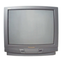
The Panasonic TX-25FG20R is a colour television designed for home entertainment. It receives and displays broadcast television signals across various global standards and supports external video and audio inputs. The television incorporates a frequency synthesizer for auto-search tuning and can store up to 100 channel positions. It features a stereo sound system and a range of video/audio terminals for connectivity.

Important Technical Specifications

  • Power Source: AC AUTO 110-240V, 50/60Hz.
  • Power Consumption: 199 W (2 W in standby).
  • Aerial Terminal: 75Ω, Coaxial type.
  • Tuning System: Frequency Synthesizer with Auto Search Tuning, supporting 100 positions.
  • Receiving Systems: 17 systems, including Regular TV and CATV.
  • Receiving Channels:
    • VHF BAND: 2-12 (PAL/SECAM B, K1), 0-12 (PAL B AUST.), 1-9 (PAL B N.Z.), 1-12 (PAL/SECAM D), 1-12 (NTSC M Japan), 2-13 (NTSC M U.S.A).
    • UHF BAND: 21-69 (PAL G, H, I/SECAM G, K, K1), 28-69 (PAL B AUST.), 13-57 (PAL D, K), 13-62 (NTSC M Japan), 14-69 (NTSC M U.S.A.).
    • CATV: S1-S20 (OSCAR), 1-125 (U.S.A. CATV), C13-C49 (JAPAN), S21-S41 (HYPER), Z1-Z37 (CHINA), 5A, 9A (AUST).
  • Intermediate Frequency: 38.0 MHz.
  • Video:
    • 31.5 MHz (D, K) / 32.5 MHz (B, G)
    • 32.0 MHz (I) / 32.5 MHz (M)
  • Sound:
    • 33.57 MHz (PAL) / 33.6 MHz (SECAM)
    • 34.42 MHz (NTSC) / 33.75 MHz (SECAM)
  • Receiving Stereo Sound System: AV STEREO.
  • Video/Audio/Terminals: AV 1, 2, 3, Y/PB/PR.
    • Y/PB/PR: Y:1.0Vp-p 75Ω, PB, PR:0.7Vp-p 75Ω.
    • Video: 1.0Vp-p 75Ω.
    • Audio: Approx. 400mV 47KΩ.
  • Monitor Out: Video 1.0Vp-p 75Ω, Audio Approx. 400mV 47KΩ.
  • High Voltage: 30.0 (+-1.0kV) at zero beam current.
  • Picture Tube: A59QDF891X Type 25 (59 cm), measured diagonally, 104° deflection.
  • Audio Output: 16 W speaker.
  • Dimensions (W x D x H): 717 mm x 502 mm x 530.5 mm.
  • Weight (Mass): 31 kg (Net).

Usage Features

The television offers a user-friendly interface for tuning and adjustments. It includes a remote control for easy access to functions like volume, channel selection, and menu navigation. The "Market Mode Function" provides service modes (Service Mode 1 and Service Mode 2) for advanced adjustments, accessible via a specific key combination on the remote and panel. These modes allow for fine-tuning of parameters such as H-POS, V-POS, H-AMP, V-AMP, EW-AMP, LOW_Corner, TRAPEZ, UPPER_Corner, V-LIN, V-SYM, ANGEL, BOW, DVCO, R-CUT OFF, G-CUT OFF, B-CUT OFF, R-DRIVE, G-DRIVE, B-DRIVE, and SUB-Bright.

Maintenance Features

The service manual outlines detailed procedures for maintenance and adjustment, intended for experienced repair technicians.

  • Safety Precautions: Emphasizes the importance of using an isolation transformer, observing original lead dress, properly installing protective devices, and discharging the picture tube anode before handling. It also details leakage current checks (cold and hot) to prevent shock hazards and provides warnings regarding X-Radiation, stressing the need for accurate high voltage measurements and using specified picture tubes.
  • Service Hints: Provides instructions on how to move the chassis into a service position, involving the removal of screws and careful manipulation of the main chassis.
  • Adjustment Procedure:
    • +B Voltage: Confirms DC voltage at specified test points (TPD 15-20) to ensure proper power supply operation.
    • RF AGC: Adjusts the RF Automatic Gain Control using a colour bar signal and remote control to achieve a specific voltage at the Tuner point (TPD 30).
    • High Voltage: Verifies +B voltage and heater voltage, then normalizes brightness and contrast.
    • NTSC TINT COLOUR: Adjusts Sub-Tint and confirms colour phase and maximum colour DAC level using an oscilloscope.
    • COLOUR PURITY: Involves setting brightness and contrast to maximum, degaussing the picture tube, applying a crosshatch pattern, adjusting static convergence magnets, and then using a green pattern signal to achieve a uniform green field at the screen's center. It also details deflection yoke adjustments.
    • CONVERGENCE: Uses a crosshatch pattern to adjust Red and Blue lines at the screen's center by rotating R-B static convergence magnets, then locking them with silicone sealer.
    • WHITE BALANCE (MARKET MODE CHK 4): Requires a colour bar signal with colour "OFF" and operating the TV for 30 minutes. It involves setting picture menu to "DYNAMIC NORMAL," adjusting G-CUTOFF to 0V at 180V video level, turning the screen control clockwise until a green horizontal line appears, adjusting R and B-CUTOFF for a white horizontal line, and finally adjusting R-Drive and B-Drive for a uniform white greyscale pattern.
    • ADJUSTMENT OF CRT VRS (FOR FLAT CRT ONLY): Involves setting the deflection yoke and CY magnet, and adjusting geomagnetic correction DAC. Then, using a white balance pattern, V-CENTER, R/B CUT OFF, and aging pattern are adjusted.
  • Schematic Diagrams: Provides detailed circuit diagrams for the GP4 Chassis, D Board, G Board, and L Board, including notes on resistor and capacitor types, test points, earth symbols, voltage measurement conditions, and signal flow. It highlights components identified with a "A" mark as having special safety characteristics, requiring manufacturer-specified parts for replacement.
  • Parts Locations: Includes diagrams showing the physical location of various components on the chassis.
  • Replacement Parts List: A comprehensive list of parts with their part numbers, descriptions, and remarks. It includes an "Important Safety Notice" for components marked with "A" and notes on "Retention Time Limited" (RTL) parts.

The manual emphasizes that specifications are subject to change without notice and that unauthorized copying and distribution of the document are a violation of law.

Panasonic TX-25FG20R Specifications

General IconGeneral
BrandPanasonic
ModelTX-25FG20R
CategoryTV
LanguageEnglish

Related product manuals