EasyManua.ls Logo

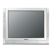
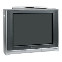
Panasonic TX-29AS10P User Manual

Panasonic TX-29AS10P
35 pages
To Next Page IconTo Next Page
Page #1 background imageLoading...
Page #1 background image
Colour Television
TX-29AS10P
EURO- 4H Chassis
SPECIFICATIONS
Power Source: 220-240V a.c., 50Hz
Power Consumption: 193W
Stand-by Power
Consumption: 1,4W
Aerial Impedance: 75 unbalanced, Coaxial Type
Receiving System: PAL B/G, H, D/K, PAL-525/60
SECAM B/G, D/K
M.NTSC (AV only)
NTSC (AV only)
Receiving Channels:
VHF E2-E12 VHF H1-H2 (ITALY)
VHF A-H (ITALY) VHF R1-R2
VHF R3-R5 VHF R6-R12
UHF E21-E69 CATV (S01-S05)
CATV S1-S10 (M1-M10) CATV S11-S20 (U1-U10)
CATV S21-S41 (HYPERBAND)
Intermediate Frequency:
Video/Audio
Video 38,9MHz
Audio 33,4MHz (B/G)
33,16MHz (A2 Stereo)
33,05MHz (NICAM)
32,4MHz (D/K)
32,66MHz (Czech Stereo)
33,16MHz (Polish Stereo)
Colour 34,47MHz (PAL)
34,5MHz, 34,65MHz (SECAM)
Terminals:
AUDIO MONITOR OUT Audio (RCAx2) 500mV rms 1k
AV1 IN Video (21 pin) 1V p-p 75
Audio (21 pin) 500mV rms 10k
RGB (21 pin) 0,7V p-p 75
AV1 OUT Video (21 pin) 1V p-p 75
Audio (21 pin) 500mV rms 1k
AV2 IN Video (21 pin) 1V p-p 75
Audio (21 pin) 500mV rms 10k
S-Video IN Y: 1V p-p 75
(21-pin) C:0,3V p-p 75
AV2 OUT Video (21 pin) 1V p-p 75
Audio (21 pin) 500mV rms 1k
AV3 IN S-Video IN Y: 1V p-p 75
(4-pin) C:0,3V p-p 75
Audio (RCAx2) 500mV rms 10k
Video (RCAx1) 1V p-p 75
High Voltage: 30,5kV ±1kV
Picture Tube: A68ELO10X71 68cm
Audio Output: 2 x 7W RMS, 2 x 15W MPO
8 Impedance
Headphones: 8 Impedance
Accessories
supplied : Remote Control
2 x R6 (UM3) Batteries
Dimensions:
Height: 579mm
Width: 688mm
Depth: 495mm
Net weight: 46kg
Specifications are subject to change without notice.
Weights and dimensions shown are approximate.
NOTE: This Service Manual should be used in conjunction with
the EURO-4H Technical guide.
ORDER No. 00-SM-026
Question and Answer IconNeed help?

Do you have a question about the Panasonic TX-29AS10P and is the answer not in the manual?

Panasonic TX-29AS10P Specifications

General IconGeneral
Screen shapeFlat
Response time- ms
Display diagonal50 \
Display brightness- cd/m²
Display technologyLED
Native aspect ratio-
Display diagonal (metric)126 cm
Supported graphics resolutions3840 x 2160
Motion interpolation technologyBMR IFC 2600 Hz
Dynamic contrast ratio marketing nameSupreme Contrast
3DYes
Annual energy consumption115 kWh
Power consumption (max)177 W
Power consumption (standby)0.5 W
Package depth140 mm
Package width1522 mm
Package height788 mm
Package weight32000 g
Digital signal format systemDVB-C, DVB-S2, DVB-T, DVB-T2
Video formats supportedH.264, H.265
On Screen Display (OSD) languagesBUL, CRO, CZE, DAN, DEU, DUT, ENG, ESP, EST, FIN, FRE, GRE, HUN, ITA, LAT, LIT, MAC, NOR, POL, POR, RUM, RUS, SER, SLK, SLV, SWE, TUR
RMS rated power- W
Product colorSilver
Panel mounting interface400 x 200 mm
PC in (D-Sub)No
HDMI ports quantity4
DVI-D ports quantity0
USB 2.0 ports quantity2
Ethernet LAN (RJ-45) ports1
Common interface Plus (CI+) version1.3
Weight and Dimensions IconWeight and Dimensions
Depth (with stand)363 mm
Height (with stand)997 mm
Weight (with stand)27000 g
Depth (without stand)40 mm
Width (without stand)1115 mm
Height (without stand)647 mm
Weight (without stand)16000 g

Summary

Product Specifications

General and Power Specifications

Details on power source, consumption, and aerial impedance.

Reception and Signal Specifications

Information on receiving systems, channels, and intermediate frequencies.

Input/Output and Audio Specifications

Specifications for AV inputs/outputs, audio output, and terminals.

Physical and Display Specifications

Details on high voltage, picture tube, dimensions, and weight.

Safety Precautions

General Safety Guidelines

Essential safety instructions for servicing, including high voltage and insulation.

Leakage Current and X-Radiation Warnings

Procedures for leakage current checks and warnings about X-Radiation.

Service Operations

Service Hints and Rear Cover Removal

Instructions for service tasks including rear cover removal.

Control and Board Identification

Locating controls and identifying major circuit boards.

Chassis Service Position

Moving Chassis for Service Access

Step-by-step guide for positioning the chassis for service.

Adjustment and Diagnostic Procedures

Adjustment Settings and Self-Check

Procedures for B+ set-up, cut-off tests, and system self-checks.

Service Aids and Utilities

Information on service tools, software, and documentation.

Waveform Pattern Table

Alignment Settings

Geometric and Picture Adjustments

Settings and procedures for geometric, cut-off, and Ug2 alignment.

Video Block Diagram

Audio Block Diagram

Control Block Diagram

Power Supply Block Diagram

Parts Location

Exploded View of Components

Visual guide to component placement using an exploded view.

Replacement Parts List - ICs, Fuses, Diodes

Exploded View Parts

List of parts corresponding to the exploded view.

Integrated Circuits (ICs)

Part numbers for integrated circuits.

Fuses, Diodes, and Miscellaneous

Catalog of fuses, diodes, and miscellaneous components.

Replacement Parts - Transistors

Transistor Components

List of transistor part numbers.

Replacement Parts - Coils, Filters, Crystals

Coil, Filter, and Crystal Components

Catalog of coil, filter, and crystal part numbers.

Replacement Parts - Resistors (Part 1)

Resistor Components (Part 1)

List of resistor part numbers and values.

Replacement Parts - Resistors (Part 2)

Resistor Components (Part 2)

Continuation of resistor part numbers and values.

Replacement Parts - Resistors (Part 3) & Capacitors (Part 1)

Resistor and Capacitor Components (Part 1)

Final resistor listings and initial capacitor part numbers.

Replacement Parts - Capacitors (Part 2)

Capacitor Components (Part 2)

Continuation of capacitor part numbers and types.

Replacement Parts - Capacitors (Part 3)

Capacitor Components (Part 3)

Further capacitor part numbers and specifications.

Replacement Parts - Capacitors (Part 4) & Terminals/Links

Capacitor and Terminal Components

Final capacitor listings and terminal/link part numbers.

Replacement Parts - Switches, Relays, Sockets

Switch, Relay, and Socket Components

List of switch, relay, and socket part numbers.

Schematic Diagram Conventions

Diagram Notes and Safety Remarks

Key to symbols, units, measurement conditions, and safety notes for diagrams.

Y-Board Schematic Diagram

E-Board Schematic Diagram

P-Board Schematic Diagram

M-Board Schematic Diagram

E-Board Schematic Diagram (Continued)

E-Board Conductor View

Y-Board Conductor View

M-Board Conductor View

F-Board Conductor View (Part 1)

F-Board Conductor View (Part 2)

P-Board Conductor View

Related product manuals